Flexible tube and production apparatus therefor

a technology of flexible tubes and production apparatuses, applied in the field of flexible tubes, can solve the problems of large number of steps and production apparatuses that are required

Active Publication Date: 2019-07-16
PLA GIKEN
View PDF23 Cites 1 Cited by
  • Summary
  • Abstract
  • Description
  • Claims
  • Application Information

AI Technical Summary

Problems solved by technology

However, the production method shown in FIG. 19 has a problem that the numbers of steps and production apparatuses that are required are large.

Method used


Image

  • Flexible tube and production apparatus therefor
  • Flexible tube and production apparatus therefor
  • Flexible tube and production apparatus therefor

Examples


first embodiment

[0038]

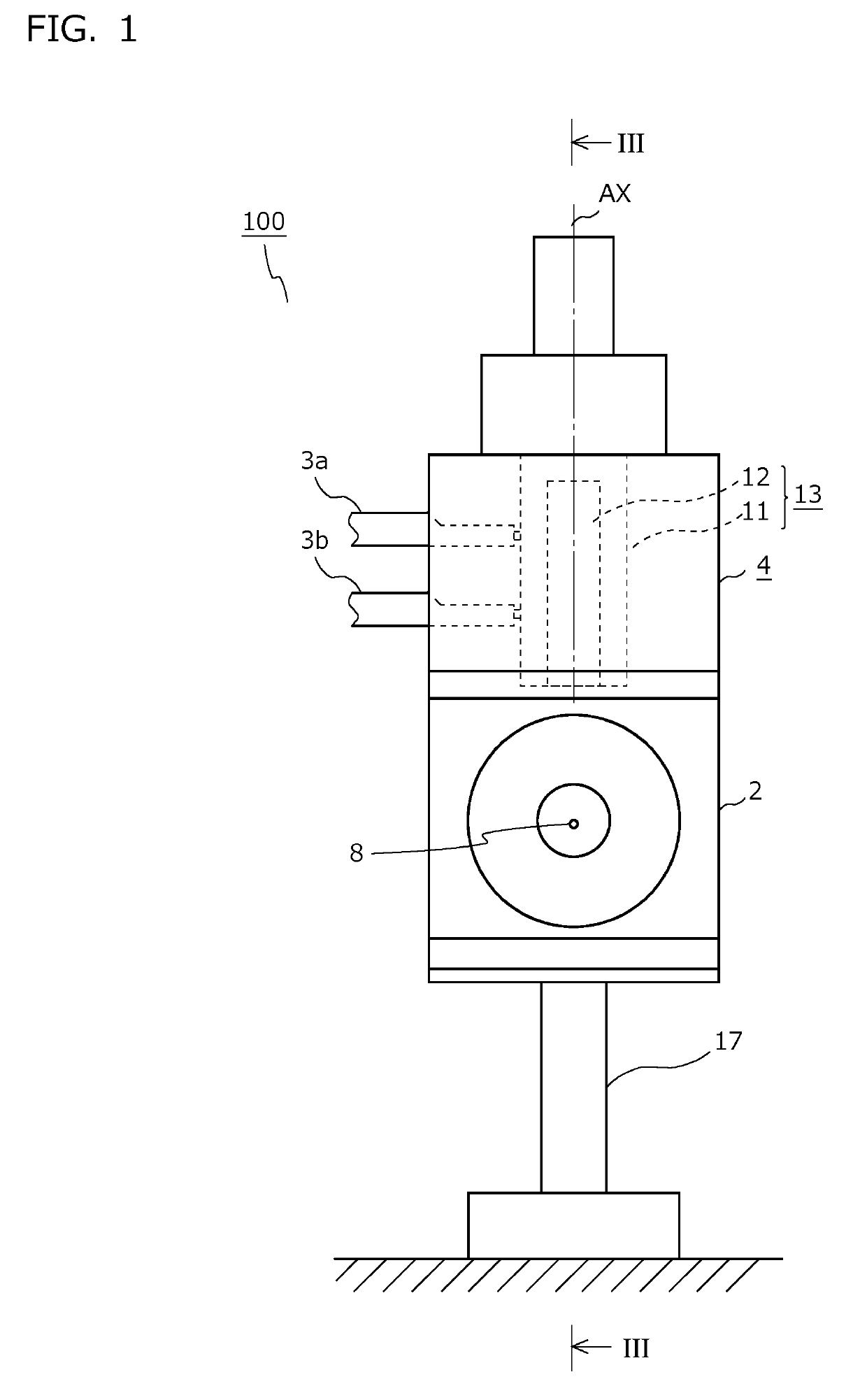
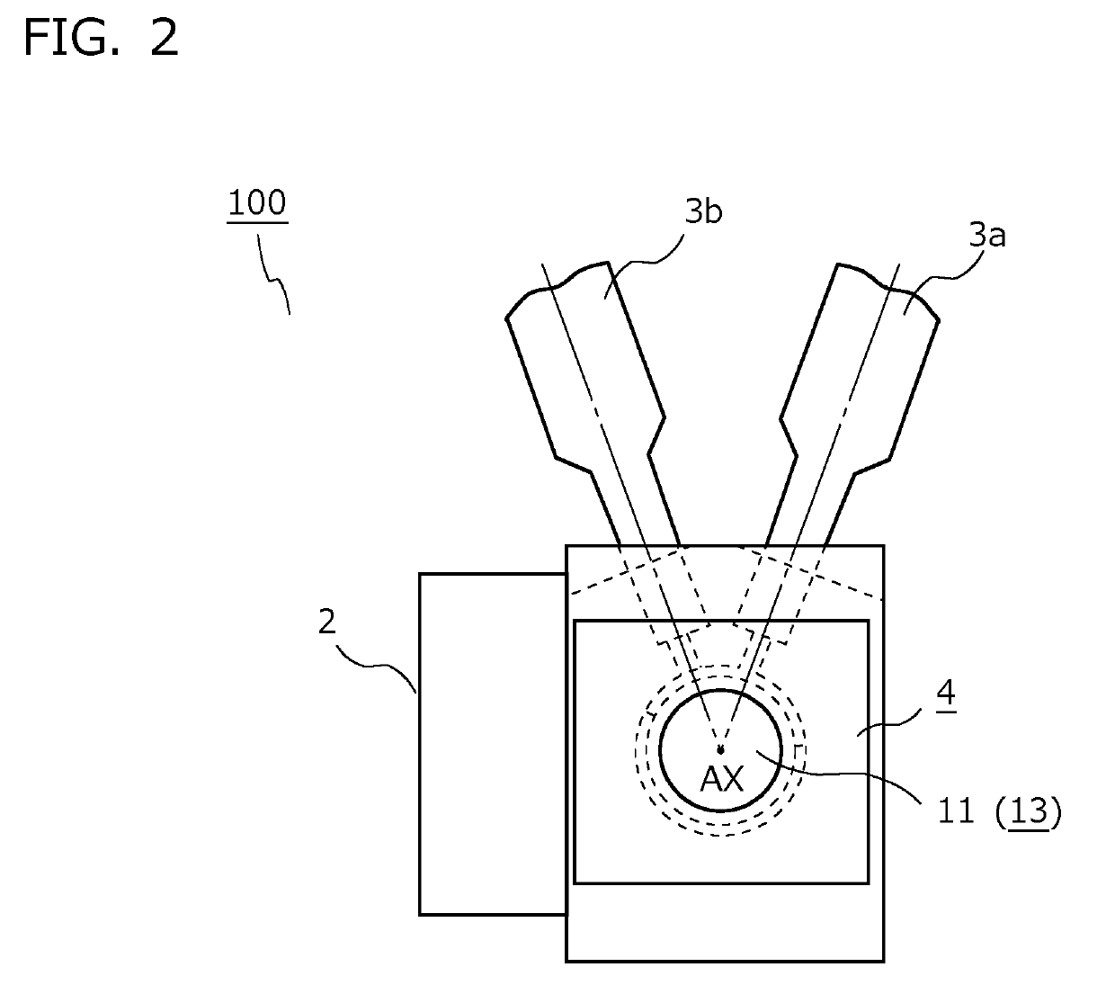
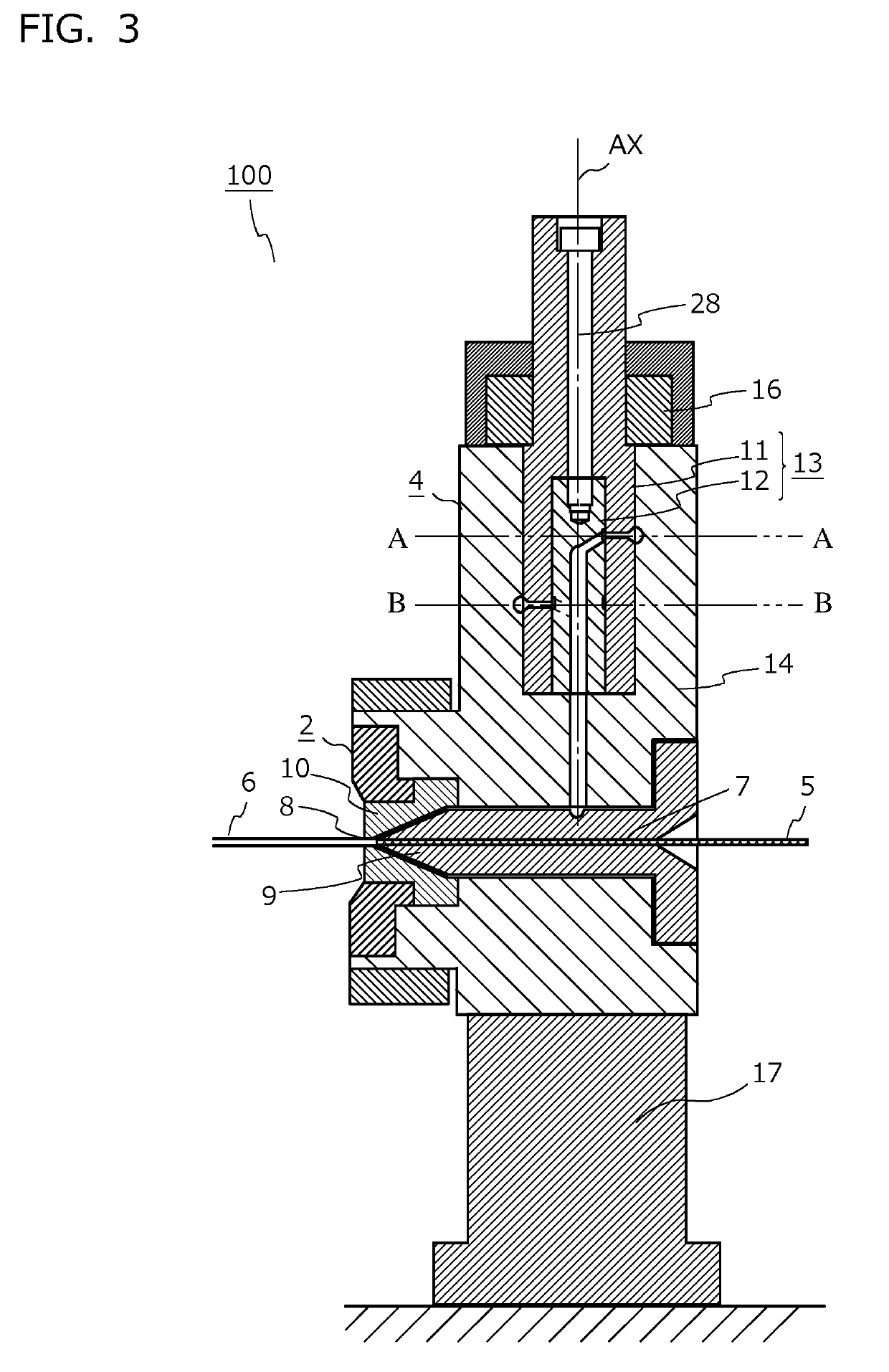
[0039]FIG. 1 is a front view of a catheter shaft production apparatus according to an embodiment. FIG. 2 is a top view of the catheter shaft production apparatus shown in FIG. 1, and FIG. 3 is a cross-sectional view thereof, taken along the line III-III shown in FIG. 1.

[0040]A catheter shaft production apparatus 100 includes a die 2, a first extruder 3a, a second extruder 3b, and a mixing valve 4. The catheter shaft production apparatus 100 is fixed to a predetermined mounting base or the like with a pedestal 17 interposed therebetween. Although not shown, a supply device for supplying a blade wire 5 to the catheter shaft production apparatus 100, a haul-off device for hauling off a catheter shaft 6 that has been extrusion-molded, and the like are provided as appropriate at the upstream side and the downstream side of the catheter shaft production apparatus 100.

[0041]As shown in FIG. 3, the die 2 includes: an inner mold 9 provided with an insertion hole 7 into which a blade wi...

second embodiment

[0101]FIG. 13 is a front view of a catheter shaft production apparatus according to a second embodiment.

[0102]In the first embodiment described above, the first valve and the second valve are formed in an integrated manner in a single valve body 13 and a single valve case 14. However, in the second embodiment, the first valve and the second valve are formed as separate bodies. Hereinafter, the difference between the present embodiment and the first embodiment is mainly described.

[0103]A catheter shaft production apparatus 200 according to the present embodiment includes: the die 2; a first extruder and a second extruder which are not shown; and the mixing valve 4, as shown in FIG. 13. The catheter shaft production apparatus 200 according to the present embodiment is also fixed to a predetermined mounting base or the like with the pedestal 17 interposed therebetween. Although not shown, a supply device for supplying the blade wire 5 to the catheter shaft production apparatus 200, a h...

third embodiment

[0118]FIG. 14 is a cross-sectional view of a catheter shaft production apparatus according to a third embodiment, and FIG. 15 is a cross-sectional view taken along the line XV-XV shown in FIG. 14.

[0119]A catheter shaft production apparatus 300 according to the third embodiment is obtained by further providing a resin mixing portion 60 to the catheter shaft production apparatus 100 according to the first embodiment shown in FIG. 1. Since configurations of the catheter shaft production apparatus 300 other than the resin mixing portion 60 are the same as those of the catheter shaft production apparatus 100 according to the first embodiment, repeated description thereof is omitted.

[0120]The resin mixing portion 60 is provided in a resin flow path extending from the junction for the resin A and the resin B to the die 2, and is a mechanism that actively mixes the resin A and the resin B together. In the present embodiment, as shown in FIG. 15, the resin mixing portion 60 is composed of: a...


PUM

PropertyMeasurementUnit
outer diameteraaaaaaaaaa
flexibleaaaaaaaaaa
constant speedaaaaaaaaaa

Abstract

Provided is a production apparatus capable of producing a flexible tube whose hardness is naturally varied along the length direction thereof. This mixing valve includes: a first valve configured to distribute a first resin to a resin supply path and a resin discharge path; and a second valve configured to distribute a second resin to the resin supply path and the resin discharge path. In the mixing valve, the mixing proportion between the first resin and the second resin is increased or decreased in association with molding of the flexible tube, by changing a distribution ratio of the first resin in the first valve and a distribution ratio of the second resin in the second valve while keeping constant the total of the supply mounts of the first resin and the second resin supplied to a die.

Description

CROSS-REFERENCE TO RELATED APPLICATION[0001]This application is a Continuation of International Application No. PCT / JP2016 / 005256, filed on Dec. 28, 2016, which in turn claims the benefit of Japanese Application No. 2016-128003 filed on Jun. 28, 2016, the disclosures of which Applications are incorporated by reference herein.BACKGROUNDField[0002]The present invention relates to a flexible tube in which the outer face of a blade is covered with a resin, and relates to a production apparatus therefor.Description of the Related Art[0003]In medical institutions, in order to inject a drug solution, a contrast medium, or the like to a predetermined site in the living body of a patient, or in order to take out body fluid or the like from the living body, a tube-shaped medical instrument called a catheter is used. Since the catheter is inserted into the living body through a winding blood vessel or the like, the leading end portion to be inserted of the catheter is required to have flexibil...

Claims


Application Information

Patent Timeline
Patent Type & Authority Patents(United States)
IPC IPC(8): A61M25/00B29C48/32B29C48/92B29C48/09B29C48/18B29C48/25B29C48/34B29C48/30B29C48/335B29C48/10B29C48/151B29C48/49B29C48/21B29C48/74B29L23/00B29L31/00
CPCA61M25/005B29C48/30A61M25/0012B29C48/09B29C48/10B29C48/151B29C48/18B29C48/2692B29C48/304B29C48/32B29C48/338B29C48/34B29C48/49B29C48/92B29C2948/92723B29C2948/92828B29C2948/92904B29C2948/92942B29K2995/002B29K2995/007B29L2023/00B29L2031/7542B29L2031/7546B29C2948/926A61M25/0053A61M25/0054B29C48/21
Inventor KIKUZAWA, YOSHIHARU
Owner PLA GIKEN
Why Eureka
Try Eureka