Tube induced deformity elimination process

a deformation elimination and tube technology, applied in the field of vacuum resin infusion, can solve the problems of visual defect in the composite part physical distortion of the dry reinforcing fiber in the preform, etc., to improve the structural performance, eliminate deformation, and improve surface appearance

Active Publication Date: 2009-09-08
THE BOEING CO
View PDF7 Cites 2 Cited by
  • Summary
  • Abstract
  • Description
  • Claims
  • Application Information

AI Technical Summary

Benefits of technology

[0007]The disclosure satisfies this need for an improved process that is unique, nonobvious, and advantageous. Unlike known processes and devices, the process provides the following advantages: produces resin infused composite parts with improved structural performance and improved surface appearance and eliminates deformation on the surface of resin infused composite parts; places the resin distribution tube above and away from the preform surface such that the tube is not affected by the downward pressure of the atmosphere; provides for flow media that connects the resin distribution tube to the preform which allows for free movement of resin without direct contact of the resin distribution tube to the preform; provides for equal forces surrounding and acting on the resin distribution tube; provides a process that produces high quality composite parts that have a better appearance, require less rework, and are structurally sounder than parts produced with known resin infusion processes because of the elimination of fiber distortion with the process of the disclosure.
[0008]In one of the embodiments of the disclosure, there is provided a process for producing resin infused composite parts having improved structural performance and improved surface appearance. The process comprises the steps of positioning a dry composite preform on a forming tool component, arranging resin exit lines in close proximity to the preform; placing a permeable release material on the perform, and placing a first piece of flow media over the release material. The process further comprises the steps of wrapping a resin distribution tube with a second piece of flow media, placing a vacuum bag layer over the forming tool component, preform, release material, first and second pieces of flow media and resin distribution tube, such that the resin distribution tube is retained in a pleat formed in the vacuum bag layer and such that a bagged preform is formed, and positioning the resin distribution tube above the bagged preform, such that the resin distribution tube is not in contact with the bagged perform.
[0009]In another one of the embodiments of the disclosure, there is provided a process for producing resin infused composite parts having improved structural performance and improved surface appearance. The process comprises the steps of positioning a dry composite preform on a forming tool component, arranging resin exit lines in close proximity to the perform, placing a permeable release material on the perform, placing a first piece of flow media over the release material. The process further comprises the steps of wrapping a resin distribution tube with a second piece of flow media, placing a vacuum bag layer over the forming tool component, preform, release material, first and second pieces of flow media and resin distribution tube, such that the resin distribution tube is retained in a pleat formed in the vacuum bag layer and such that a bagged preform is formed, and positioning the resin distribution tube above the bagged preform, such that the resin distribution tube is not in contact with the bagged perform. The process further comprises the steps of infusing resin into the bagged preform through the resin distribution tube and first and second pieces of flow media and returning an excess resin to a reservoir, and curing the resin infused bagged perform.
[0010]In another embodiment of the disclosure, there is provided a process for producing resin infused composite parts having improved structural performance and improved surface appearance. The process comprises the steps of positioning a resin distribution tube used in a controlled atmospheric pressure resin vacuum infusion process above the surface of a preform layered with a permeable release material and a first piece of flow media, wrapping the resin distribution tube in a second piece of flow media, and wrapping and suspending the resin distribution tube in a pleat of a vacuum bag layer covering the preform and the resin distribution tube, such that the resin distribution tube is not in contact with the preform.

Problems solved by technology

Such deformation or mark-off not only causes a visual defect in the composite part but also causes a physical distortion of the dry reinforcing fibers in the preform.
Such physical distortion can affect the mechanical performance of the composite part, including such mechanical performance properties as tensile properties and compression properties.
However, although the use of a wider area may reduce the pressure in a concentrated area, the deformation or mark-off problem is merely transferred to a wider area because there is still direct contact between the resin distribution tube and the preform.

Method used


Image

  • Tube induced deformity elimination process
  • Tube induced deformity elimination process
  • Tube induced deformity elimination process

Examples


Embodiment Construction

[0020]The disclosure now will be described more fully hereinafter with reference to the accompanying drawings, in which some, but not all embodiments of the disclosure are shown. Indeed, this disclosure may be embodied in several-different forms and should not be construed as limited to the embodiments set forth herein. Rather, these embodiments are provided so that this disclosure will be thorough and complete and will fully convey the scope of the disclosure to those skilled in the art. Like numbers refer to like elements throughout.

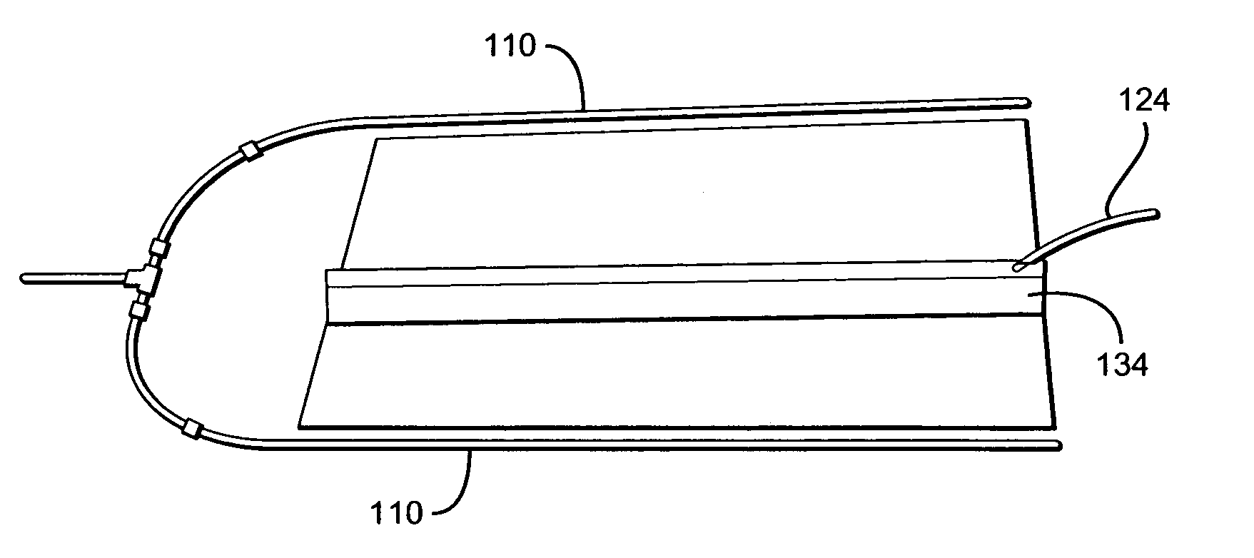
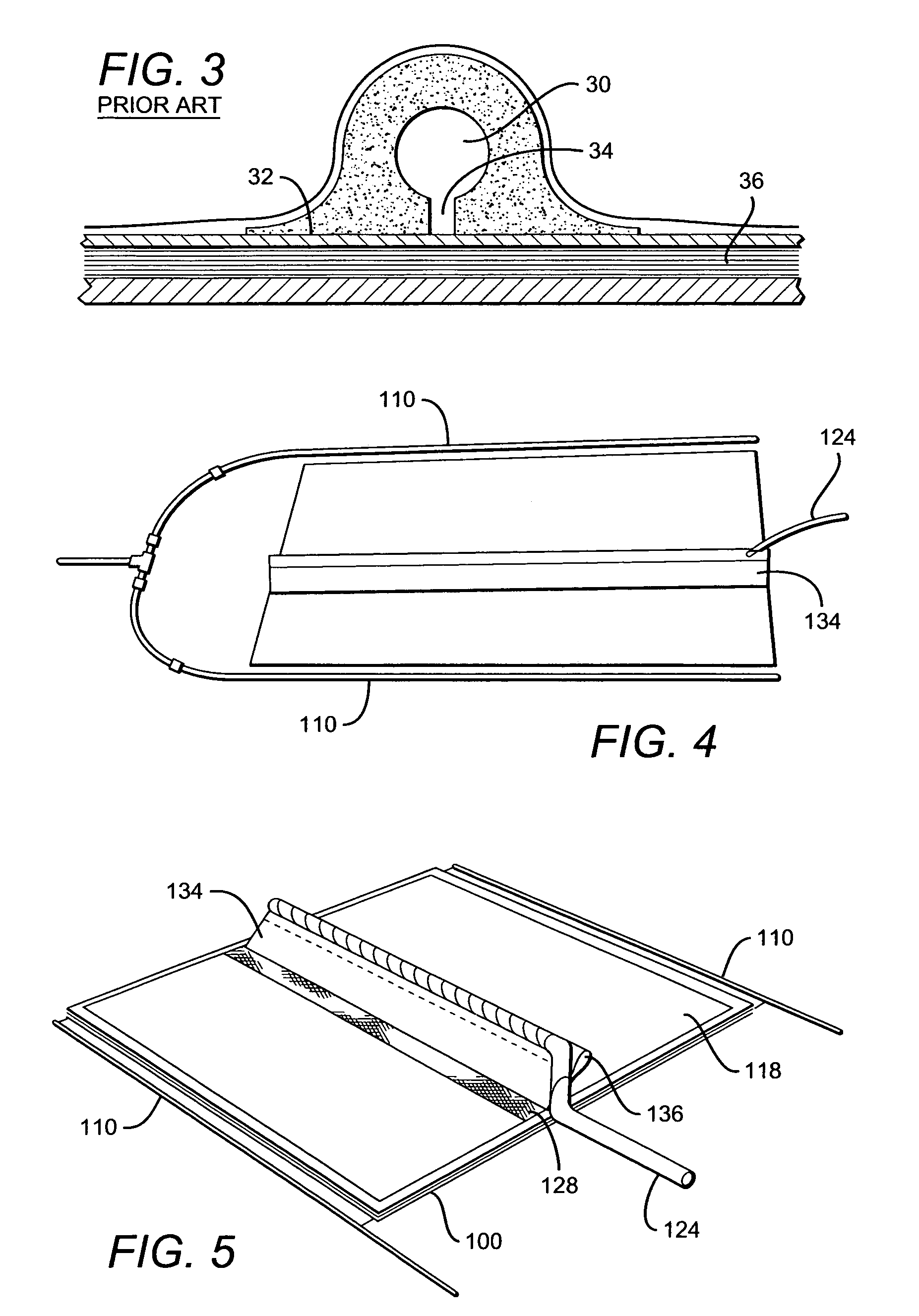
[0021]Referring to the FIGS., FIG. 4 is an illustration of a top view of one of the embodiments of the tube induced deformity elimination (TIDE) process of the disclosure. FIG. 5 is an illustration of a perspective view of the one of the embodiments of the process of the disclosure. FIG. 6 is an illustration of a front sectional view of the process of FIG. 5. The disclosure provides for a process for producing resin infused composite parts having impro...


PUM

PropertyMeasurementUnit
angleaaaaaaaaaa
angleaaaaaaaaaa
temperatureaaaaaaaaaa

Abstract

The disclosure is directed to a process for producing resin infused composite parts having improved structural performance and improved surface appearance. The process comprises the steps of positioning a dry composite preform on a forming tool component, arranging resin exit lines in close proximity to the perform, placing a permeable release material on the perform, and placing a first piece of flow media over the release material. The process further comprises the steps of wrapping a resin distribution tube with a second piece of flow media, placing a vacuum bag layer over the forming tool component, preform, release material, first and second pieces of flow media and resin distribution tube, such that the resin distribution tube is retained in a pleat formed in the vacuum bag layer and such that a bagged preform is formed, and positioning the resin distribution tube above the bagged preform.

Description

BACKGROUND[0001]1. Field[0002]The disclosure relates to a process for making composite parts. In particular, the disclosure relates to a vacuum resin infusion for making fiber-reinforced resin composite parts.[0003]2. Description of Related Art[0004]Vacuum resin infusion is a process for making high quality composite parts used in the aerospace, automotive, marine, trucking, rail, defense, and other industries. Composite parts manufactured with known vacuum resin processes have a high strength and stiffness, are resistant to fatigue and chemical attack, and are corrosion-free or corrosion-resistant. Such a known vacuum resin infusion process is the controlled atmospheric pressure resin infusion (CAPRI) process. FIG. 1 is a schematic drawing of the known CAPRI process. In this process, as shown in FIG. 1, a reduced pressure vacuum is placed on an inlet reservoir 10. A vacuum pump operating at the exit of a vacuum bag layer 14 reduces the pressure at the outlet to essentially full vac...

Claims


Application Information

Patent Timeline
Patent Type & Authority Patents(United States)
IPC IPC(8): B29C70/44
CPCB29C70/548B29C70/443
Inventor HANKS, DENNIS J.WOODS, JACK A.FELDE, KATE J.
Owner THE BOEING CO
Why Eureka
Try Eureka