
Resin dispensing device

A coating device and resin technology, which is applied to devices and coatings that apply liquid to surfaces, can solve problems such as inability to continuously discharge resin, inability to discharge resin, and differences

Inactive Publication Date: 2015-03-25
株式会社头梧择
View PDF6 Cites 1 Cited by
  • Summary
  • Abstract
  • Description
  • Claims
  • Application Information

AI Technical Summary

Problems solved by technology

[0006] However, in the resin coating device disclosed in Korean Patent No. 1082999, when it is used for a long time or restarted after supplying resin into the syringe, air is formed between the filled resin and the piston member in the resin filling cylinder. layer, the piston member presses the air layer to push the filled resin downward, so a certain amount of resin cannot be continuously discharged
[0007] That is, the force with which the piston member pushes the resin is constant, but when there is an air layer in the resin filling cylinder and when there is no air layer, the thickness of the formed air layer is different from the force that the piston member pushes the resin. With a certain force, there is a difference in the amount of resin pushed downward, and finally, a certain amount of resin cannot be discharged

Method used


Image

  • Resin dispensing device
  • Resin dispensing device
  • Resin dispensing device

Examples


Embodiment Construction

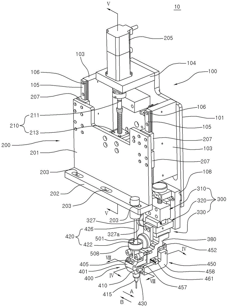
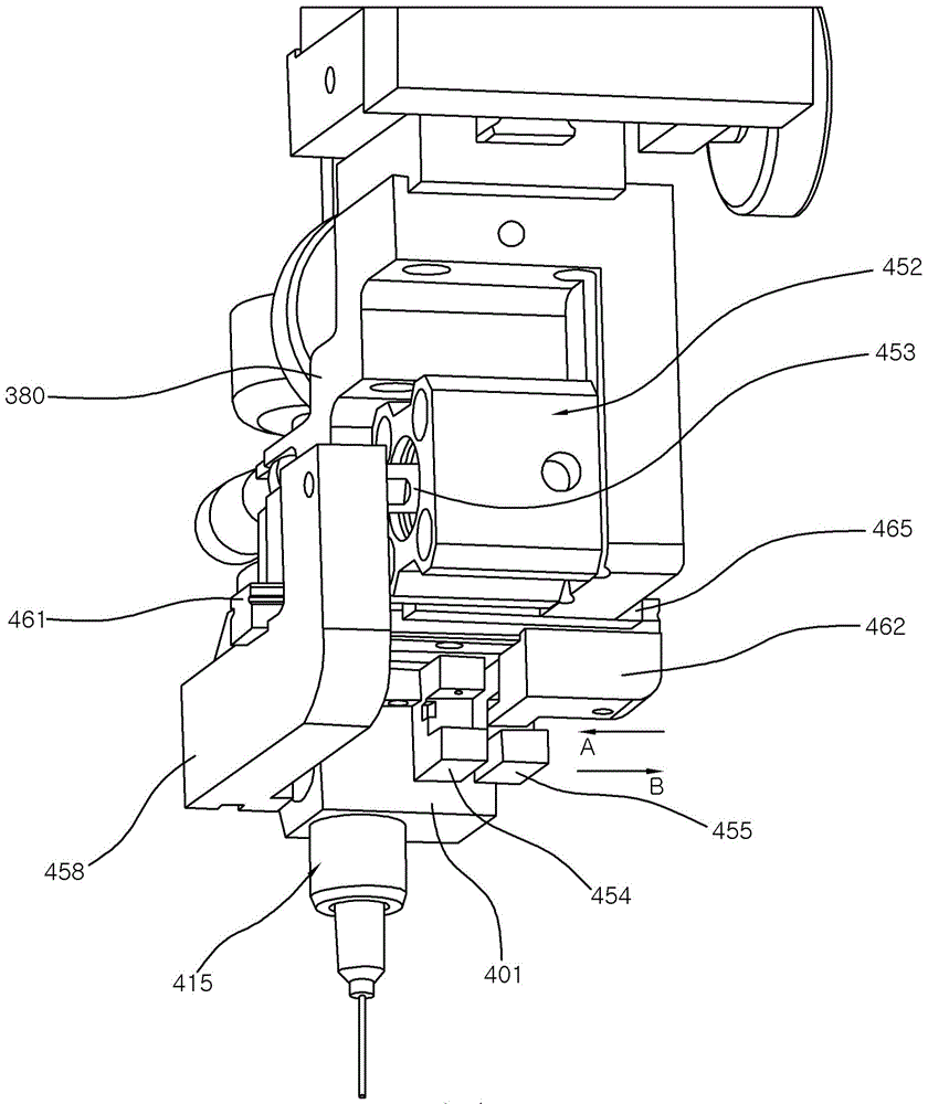
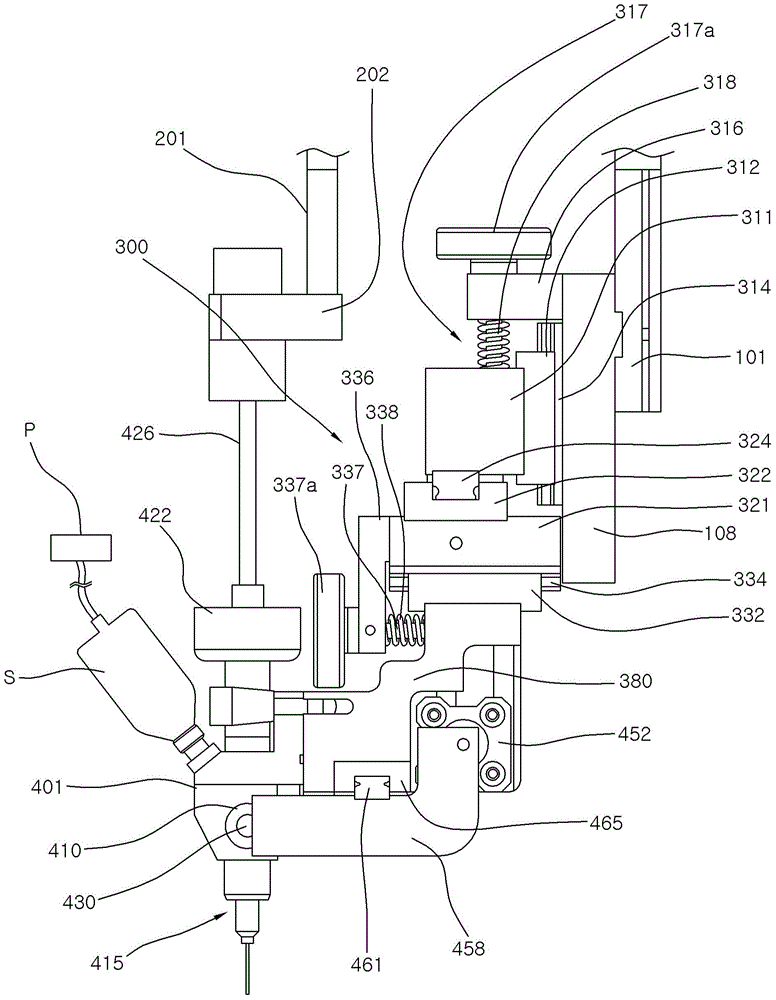
[0028] Next, a resin coating device 10 according to an embodiment of the present invention will be described with reference to the drawings. in addition, figure 1 is a perspective view of a resin coating device according to an embodiment of the present invention except for a syringe, figure 2 is viewed from the back figure 1 A perspective view of a part of the resin coating apparatus shown, image 3 yes figure 1 A schematic view of the right part of the syringe provided in the resin coating apparatus shown.

[0029] The resin coating device 10 includes a base part 100 , a vertical movement part 200 , a position adjustment unit 300 , and a coating head unit 400 .

[0030] For the base 100, the base plate 101 is installed on a common robot unit and is connected to a drive head that can move along the X-Y-Z axis. On both sides of the base plate 101, a pair of guide rails are connected along the upper and lower length directions in a manner protruding forward. Bracket 103. ...


PUM


Abstract

The invention provides a resin dispensing device having a dispensing head unit. The abovementioned dispensing head unit includes: a dispensing head main body; a needle component; a resin injection portion; an injector; and a flow path changer lever arranged to be able to slide inside the abovementioned dispensing head main body and to selectively communicate the abovementioned resin filling cylinder and the abovementioned needle component or communicate the abovementioned resin filling cylinder and the abovementioned injector, when the abovementioned resin filling cylinder is communicated with the abovementioned injector, resin housed in the abovementioned injector is filled in the abovementioned resin filling cylinder, and when the abovementioned resin filling cylinder is communicated with the abovementioned needle component, resin filled in the abovementioned resin filling cylinder is discharged through the abovementioned needle component, the abovementioned resin injection portion includes a piston component which is slidably arranged inside the abovementioned resin filling cylinder and pushes resin filled in the abovementioned resin filling cylinder towards a lower part, and an exhaust vent which discharges air outwards when resin is filled is formed at one side of an upper end part of the abovementioned resin filling cylinder.

Description

technical field [0001] The present invention relates to a resin coating device for coating epoxy resin on components such as chips and IC chips mounted on a lead frame, and more particularly, to a resin coating device capable of coating a certain amount of resin by improving the structure. Background technique [0002] In general, resin coating devices (coating machines) suitable for the following processes are widely used in various technologies: In order to mount surface mount components (chips, ICs) on printed circuit boards (PCB: Printed Circuit Board), coating (Dispensing) Viscous solution such as epoxy resin, or in order to protect the semiconductor element from the external environment, coat and encapsulate the edge of the chip (chip), and underfill the flip chip (underfill). [0003] Korean Patent No. 10-0578693 discloses a structure in which the resin contained in the syringe is pressurized by the injection pressure of the pump method, and the tip of the point rod m...

Claims


Application Information

Patent Timeline
Patent Type & Authority Applications(China)
IPC IPC(8): B05C5/02B05C11/10
CPCB05C5/02B05C5/0225B05C11/10
Inventor 刘永敦金镇洙
Owner 株式会社头梧择
Learn More