Coefficient-of-thermal-expansion measurement method of dimension reference gauge, measuring device for coefficient of thermal expansion and reference gauge

a measurement method and thermoelectric expansion technology, applied in the direction of measurement devices, mechanical measuring arrangements, instruments, etc., can solve the problems of high cost of the entire system, high cost of the optical interferometer per se, and high cost of the optical interferometer, so as to achieve high accuracy and inexpensive measurement

Active Publication Date: 2019-07-16
MITUTOYO CORP
View PDF22 Cites 3 Cited by
  • Summary
  • Abstract
  • Description
  • Claims
  • Application Information

AI Technical Summary

Benefits of technology

[0041]An object of the invention is to provide a coefficient-of-thermal-expansion (CTE) measurement method and a measuring device for coefficient of thermal expansion (CTE measuring device) capable of highly accurately and inexpensively measuring a CTE of dimension reference gauges of various lengths.

Problems solved by technology

However, such a length measurement using the optical interferometer requires a high cost for the optical interferometer.
Specifically, not only the optical interferometer per se is expensive, but also reflectivity of air has to be calculated in order to calibrate the wavelength of the measurement light, which entails measurement apparatuses for environment (e.g. temperature, humidity, atmospheric pressure and carbon dioxide concentration).
Thus, the cost of the entire system becomes expensive.
In other words, it is difficult to apply the above method in measurement of dimensions between protrusions at a middle portion of a reference gauge having comb-shaped measurement faces (e.g. a step gauge).
However, the measurable length is fixed by the pinching unit in the above-described method disclosed in Patent Literature 3 and it is not possible to measure a wide variety of lengths (e.g. length of the middle portion).
Further, since a pinching unit of a correspondingly large size has to be prepared for a long step gauge, applicability of the method is limited.
Further, since the output of the strain gauge contains noise components, it is difficult to extract only the CTE of the step gauge from the converted length.
However, even when a coordinate measuring machine is used for the length measurement as in the method disclosed in Patent Literature 2, measurement accuracy may be deteriorated when the above-described large step gauge with the length of 1.5 m or more is measured.
In addition, complicated processes of exchanging the reference gauge in the temperature-controlled chamber and then setting the temperature-controlled chamber at a plurality of temperatures in order to measure each of the section lengths at the plurality of temperatures are required.
The measurement of CTE accompanying the exchanging of the reference gauge becomes extremely complicated.
Among the above, preparation of a dedicated gauge block having a length exceeding 1000 mm and a sufficient accuracy entails considerable increase in the measurement cost and thus is not applicable.
However, when a temperature variation occurs as in the measurement of CTE, the tight adhesion of the combined gauge blocks becomes unstable.
Thus, it has been difficult to use the combined plurality of gauge blocks as a reference gauge for measuring the CTE.

Method used


Image

  • Coefficient-of-thermal-expansion measurement method of dimension reference gauge, measuring device for coefficient of thermal expansion and reference gauge
  • Coefficient-of-thermal-expansion measurement method of dimension reference gauge, measuring device for coefficient of thermal expansion and reference gauge
  • Coefficient-of-thermal-expansion measurement method of dimension reference gauge, measuring device for coefficient of thermal expansion and reference gauge

Examples


first exemplary embodiment

Advantages of First Exemplary Embodiment

[0254]The above-described first exemplary embodiment offers the following advantages.

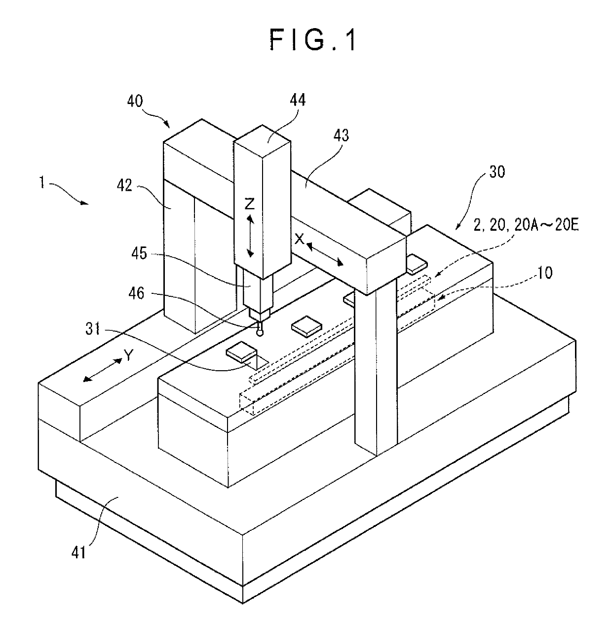
[0255]Since the length of the step gauge 10 (measurement target) is measured using the coordinate measuring machine 40, the CTE of the step gauge 10 having various lengths can be highly accurately measured without using an expensive optical interferometer.

[0256]Further, in the first exemplary embodiment, the reference gauge block 2 is used as a length master and the relative measurement of the length with respect to the reference gauge block 2 is performed in measuring the length of the step gauge 10 using the coordinate measuring machine 40. Accordingly, the results of the length measurement are not dependent on the accuracy of the scale of the coordinate measuring machine 40 but are solely dependent on the accuracy of the reference gauge block 2. Thus, high accuracy of the measurement results can be ensured even when the length of the step gauge 10 is increa...

second exemplary embodiment

[0269]FIG. 13 shows a second exemplary embodiment of the invention.

[0270]In the above-described first exemplary embodiment, the conical hole 619 and the V-shaped groove 628 are directly formed on the lower face of the reference gauge block 2 in order to support the reference gauge block 2 using the first reference gauge support base 61 and the second reference gauge support base 62.

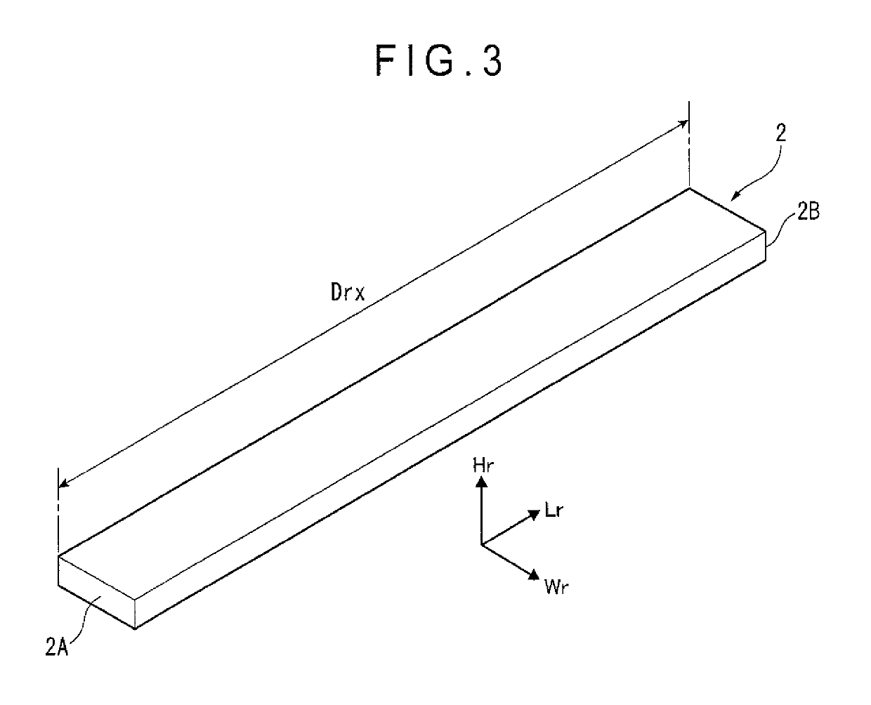
[0271]In contrast, support adapters 71, 72 are attached to the reference gauge block 2 in the second exemplary embodiment as shown in FIG. 3 and the conical hole 619 and the V-shaped groove 628 are formed on the lower faces of the support adapters 71, 72.

[0272]It should be noted that the arrangement of the second exemplary embodiment is the same as the above-described first exemplary embodiment except for the support arrangement of the reference gauge block 2 and duplicated description will be omitted. Only the difference will be described below.

[0273]It should further be noted that, though the support ad...

third exemplary embodiment

[0280]FIGS. 14 and 15 show a third exemplary embodiment of the invention.

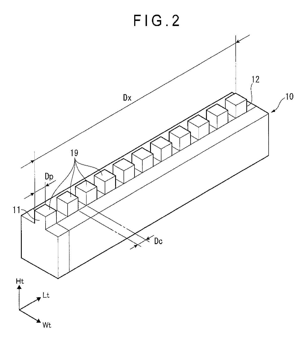
[0281]In the above-described first exemplary embodiment, the measurement aperture 31 for introducing the probe 46 is provided on the upper face of the temperature-controlled chamber 30 and the protrusions 19 are provided to the upper face of the step gauge 10 (i.e. at the side facing the measurement apertures 31) and the reference gauge block 2 is provided in parallel to and above the step gauge 10 inside the temperature-controlled chamber 30.

[0282]In contrast, as shown in FIGS. 14 and 15, measurement apertures 31A into which the probe 46 is configured to be introduced are provided on one of lateral faces of the temperature-controlled chamber 30A, the step gauge 10 is disposed along the one of the lateral faces and the reference gauge block 2 is disposed between the one of the lateral faces and the step gauge 10 in parallel to each other.

[0283]The third exemplary embodiment offers the same advantages as those m...


PUM

PropertyMeasurementUnit
lengthaaaaaaaaaa
lengthaaaaaaaaaa
lengthaaaaaaaaaa

Abstract

A measurement target and a reference gauge are placed in parallel in an inside of a temperature-controlled chamber. After an interior temperature of the temperature-controlled chamber is set at a first temperature, a relative measurement of a length from a first surface to a second surface of the measurement target is performed with reference to a length from a first reference surface to a second reference surface of the reference gauge. Then, the interior temperature of the temperature-controlled chamber is set at a second temperature and a relative measurement of the length from the first surface to the second surface is similarly performed with reference to the length from the first reference surface to the second reference surface. A CTE of the measurement target is calculated based on the length of the measurement target at the first temperature and the length of the measurement target at the second temperature.

Description

[0001]The entire disclosure of Japanese Patent Applications No. 2015-188093 filed Sep. 25, 2015, No. 2015-215240 filed Oct. 30, 2015, and No. 2015-215241 filed Oct. 30, 2015 is expressly incorporated by reference herein.TECHNICAL FIELD[0002]The present invention relates to a coefficient-of-thermal-expansion measurement method of a dimension reference gauge, a measuring device for coefficient of thermal expansion (CTE measuring device) and a reference gauge.BACKGROUND ART[0003]Dimension reference gauges are used in testing measuring devices such as coordinate measuring machines.[0004]Step gauges corresponding to a plurality of lengths as well as various gauge blocks whose end-to-end dimension is highly accurately calibrated are used for the dimension reference gauge.[0005]The step gauges are comb-shaped components having alternately arranged protrusions and recesses, where a plurality of reference dimensions are defined between end faces of the protrusions. The step gauges are produc...

Claims


Application Information

Patent Timeline
Patent Type & Authority Patents(United States)
IPC IPC(8): G01B5/008G01N25/16
CPCG01N25/16G01B5/008G01B3/02
Inventor YOKOYAMA, YUICHIROHAGINO, TAKESHIKURIYAMA, YUTAKA
Owner MITUTOYO CORP
Why Eureka
Try Eureka