Low-field magnetic resonance imaging methods and apparatus

a magnetic resonance imaging and low-field technology, applied in the field of low-field magnetic resonance imaging methods and apparatuses, can solve the problems of limited availability and/or difficulty in gaining access to clinical mri scanners, relative high equipment cost, and/or the length of the image acquisition process

Active Publication Date: 2019-07-16
HYPERFINE OPERATIONS INC
View PDF55 Cites 58 Cited by
  • Summary
  • Abstract
  • Description
  • Claims
  • Application Information

AI Technical Summary

Problems solved by technology

However, there are a number of drawbacks to MRI that, for a given imaging application, may involve the relatively high cost of the equipment, limited availability and / or difficulty in gaining access to clinical MRI scanners and / or the length of the image acquisition process.

Method used


Image

  • Low-field magnetic resonance imaging methods and apparatus
  • Low-field magnetic resonance imaging methods and apparatus
  • Low-field magnetic resonance imaging methods and apparatus

Examples


Embodiment Construction

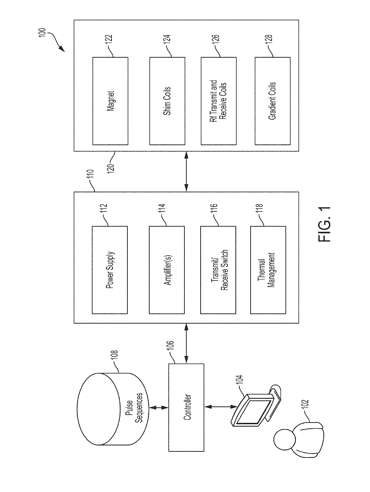
[0088]The MRI scanner market is overwhelmingly dominated by high-field systems, and particularly for medical or clinical MRI applications. As discussed above, the general trend in medical imaging has been to produce MRI scanners with increasingly greater field strengths, with the vast majority of clinical MRI scanners operating at 1.5 T or 3 T, with higher field strengths of 7 T and 9 T used in research settings. As used herein, “high-field” refers generally to MRI systems presently in use in a clinical setting and, more particularly, to MRI systems operating with a main magnetic field (i.e., a B0 field) at or above 1.5 T, though clinical systems operating between 0.5 T and 1.5 T are often also characterized as “high-field.” Field strengths between approximately 0.2 T and 0.5 T have been characterized as “mid-field” and, as field strengths in the high-field regime have continued to increase, field strengths in the range between 0.5 T and IT have also been characterized as mid-field....


PUM


Abstract

An apparatus for providing a B0 magnetic field for a magnetic resonance imaging system, the apparatus comprising: at least one permanent B0 magnet to produce a magnetic field to contribute to the B0 magnetic field for the magnetic resonance imaging system, the at least one permanent B0 magnet comprising a plurality of permanent magnet rings, each of the plurality of permanent magnet rings comprising a plurality of permanent magnet segments having a respective height in a direction normal to the respective permanent magnet ring, wherein the height of at least one first permanent magnet segment is different than the height of at least one second permanent magnet segment, and wherein the at least one first permanent magnet segment and the at least one second permanent magnet are in different ones of the plurality of permanent magnet rings.

Description

CROSS REFERENCE TO RELATED APPLICATIONS[0001]This application claims priority under 35 U.S.C. § 120 and is a continuation (CON) of U.S. application Ser. No. 15 / 956,522, filed Apr. 18, 2018 and titled LOW-FIELD MAGNETIC RESONANCE IMAGING METHODS AND APPARATUS, which claims priority under 35 U.S.C. § 120 and is a continuation-in-part (CIP) of U.S. application Ser. No. 15 / 821,207, filed Nov. 22, 2017 and titled LOW-FIELD MAGNETIC RESONANCE IMAGING METHODS AND APPARATUS, which claims priority under 35 U.S.C. § 119 to U.S. Provisional Application Ser. No. 62 / 425,465, filed Nov. 22, 2016, and titled LOW-FIELD MAGNETIC RESONANCE IMAGING METHODS AND APPARATUS, and which claims priority under 35 U.S.C. § 120 and is a continuation-in-part (CIP) of U.S. application Ser. No. 15 / 640,369, filed Jun. 30, 2017 and titled “LOW-FIELD MAGNETIC RESONANCE IMAGING METHODS AND APPARATUS,” which also claims priority under 35 U.S.C. § 119 to U.S. Provisional Application Ser. No. 62 / 425,465, filed Nov. 22, 2...

Claims


Application Information

Patent Timeline
Patent Type & Authority Patents(United States)
IPC IPC(8): G01R33/38A61B6/00G01R33/56A61B5/055A61B50/13A61B90/00G01R33/385G01R33/383G01R33/44G01R33/389G01R33/421A61G13/10G01R33/34G01R33/48G01R33/422G01R33/36G01R33/3873
CPCG01R33/3852A61B6/4405A61B50/13A61B90/00A61G13/104G01R33/34092G01R33/38G01R33/383G01R33/389G01R33/4215G01R33/445G01R33/48G01R33/5608A61B5/0555G01R33/422A61B2560/0431G01R33/3642G01R33/3657G01R33/3802G01R33/385G01R33/3806G01R33/3854G01R33/3873A61B5/055
Inventor POOLE, MICHAEL STEPHENHUGON, CEDRIC
Owner HYPERFINE OPERATIONS INC
Why Eureka
Try Eureka