Electrical switch, in particular a switch for an electrical power tool

a technology of electrical power tools and switches, applied in the direction of relays, electromagnetic relay details, contact mechanisms, etc., can solve the problems of unintended restart of the switch in which it is used, unattended, hazardous situations for the user of the electric power tool, etc., and achieve the effect of simple design

Active Publication Date: 2019-07-16
MARQUARDT VERW
View PDF17 Cites 0 Cited by
  • Summary
  • Abstract
  • Description
  • Claims
  • Application Information

AI Technical Summary

Benefits of technology

[0004]The present invention is based on the object of further developing the switch in such a manner that a restart protection for the electric power tool is provided on the switch and, in particular, with the switch being of a simple design.
[0011]In a development of particularly simple design, the coupling element may consist of a rotary disk, rotary pin, rotary lever or the like. In a simple and compact manner, a coupling region may be provided, in the manner of a gate element on the plunger and / or on the coupling element. The coupling element can thereby be moved into the second position in the case of resetting of the plunger that is out of interaction with the contact piece.
[0015]The restart protection prevents an appliance, when locked in the ON position, from starting up again in an unintended manner and / or when unattended following failure and restoration of the mains electric power supply, and thus from being able to create hazardous situations for the user.
[0037]The advantages achieved with the present invention consist, in particular, in that the switch fulfills the requirement, arising from the amended appliance standard, for a restart protection. As a result of the restart protection being integrated in the switch, no alteration, or only very little alteration, of the design of the appliance and / or of the appliance wiring is required. The switch according to the present invention with restart protection can easily be substituted for a conventional switch without restart protection. The appliance manufacturers can thus use the same appliance platform for countries in which the restart protection is prescribed and for those in which it is not required. The proposed solution is equally suitable for paddle actuation and for slide actuation of the appliance. Furthermore, there is increased added value in comparison with a simple switch without restart protection. In comparison with a solution with a separate electronic module for the restart protection, the wiring and assembly of the device having a switch according to the present invention is considerably more simple and cost-effective. In this case, there are no additional wires and / or connections.

Problems solved by technology

It has been found that, in the case of failure and subsequent restoration of the voltage supply, a switched-on electric power tool in which such a switch is used may start up again in an unintended manner and / or when unattended.
This may result in hazardous situations for the user of the electric power tool.
In particular, there is the risk of such a re-start if the electric power tool is provided with a device for locking the actuating means in the on position of the contact system.

Method used


Image

  • Electrical switch, in particular a switch for an electrical power tool
  • Electrical switch, in particular a switch for an electrical power tool
  • Electrical switch, in particular a switch for an electrical power tool

Examples


Embodiment Construction

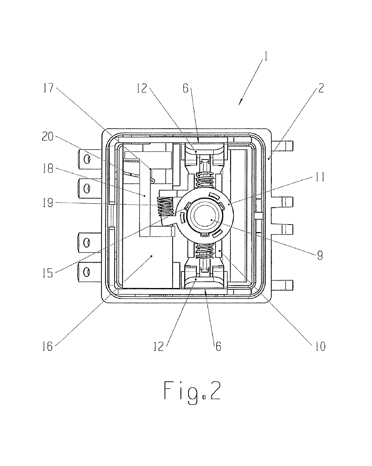
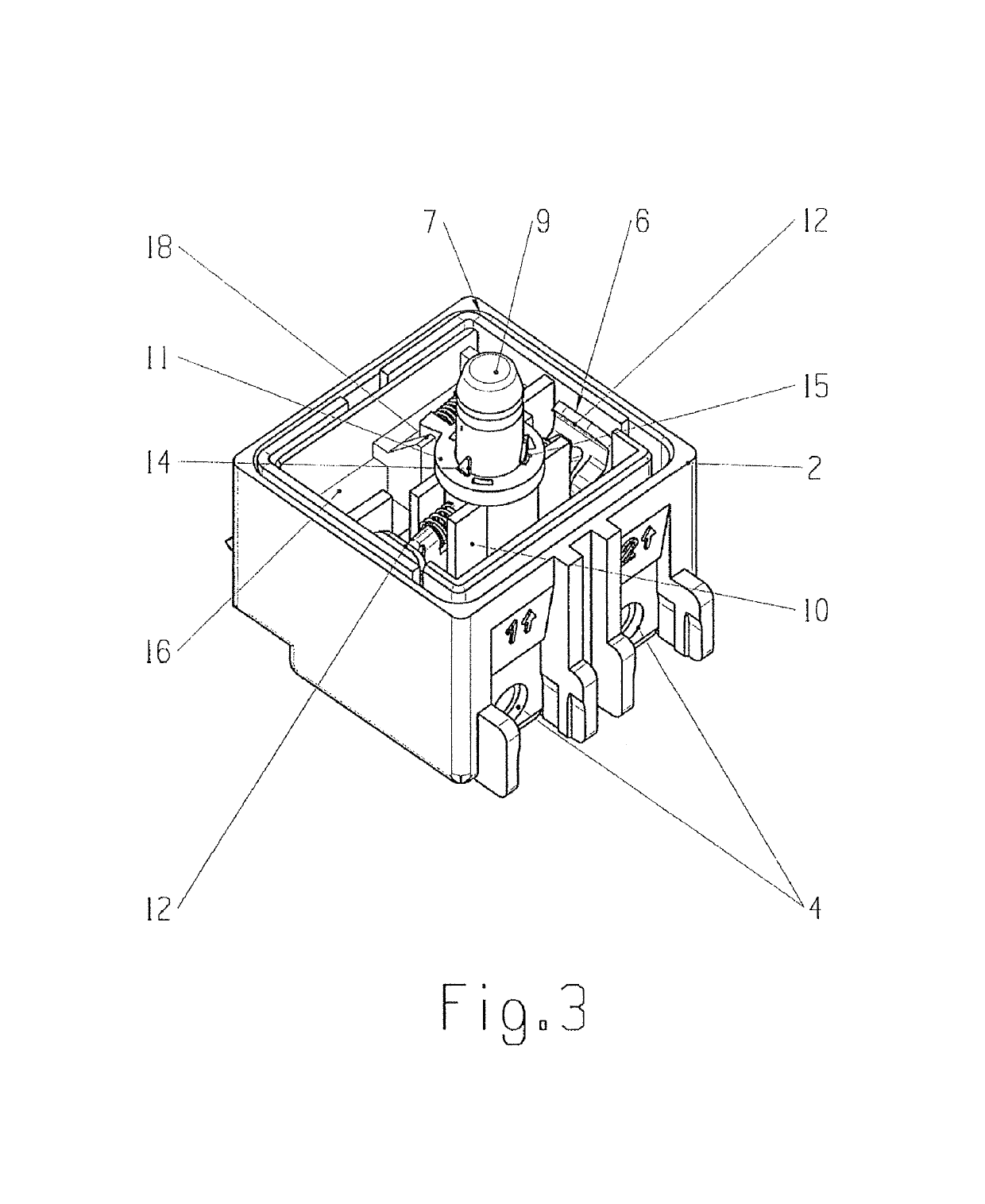
[0056]FIG. 1 shows an electrical switch 1 for an electric power tool operated by means of mains supply voltage. The switch 1 has a contact system 6 and serves as an on / off switch for the electric motor 22 of the electric power tool 21, as is further shown by FIG. 21. At least one electrical connection 4 is provided for supplying the voltage, i.e. the mains supply voltage, to the contact system 6. Also provided is at least one further electrical connection 5, for taking off the voltage switched by means of the contact system 6, this voltage then being supplied to the electric motor 22. Finally, the switch 1 has a movable actuating means 7 for switching the contact system 6.

[0057]The actuating means 7, for its part, is moved by an actuating element 23 that is present on the electric power tool 21 and that can be moved, according to the double arrow 24, by the user, the switch 1 actuated indirectly. In the corresponding actuation position of the actuating element 23, in which the switc...


PUM


Abstract

An electrical switch for an electric power tool. The electrical switch has a contact system that can be switched between an off position and an on position, and having a movable actuating means or switching the contact system. The actuating means comprises a plunger and a contact piece. The contact piece acts on the contact system for the purpose of switching. A coupling element is provided, such that the plunger can be brought into and out of interaction with the contact piece. The interaction is effected such that it is made possible for the contact system to be switched into the on position and the off position by means of the plunger, and for the contact system to be switched into the off position independently of the plunger.

Description

FIELD OF THE INVENTION[0001]The invention relates to an electrical switch.BACKGROUND OF THE INVENTION[0002]The principal use of such electrical switches is for an electric power tool. These electric power tools may be angle grinders, power drills, sanders, saws, planes or the like.[0003]Known from DE 44 37 020 A1 is an electrical switch having a contact system that can be switched between an off position and an on position. The switch additionally has a movable actuating means for switching the contact system. It has been found that, in the case of failure and subsequent restoration of the voltage supply, a switched-on electric power tool in which such a switch is used may start up again in an unintended manner and / or when unattended. This may result in hazardous situations for the user of the electric power tool. In particular, there is the risk of such a re-start if the electric power tool is provided with a device for locking the actuating means in the on position of the contact ...

Claims


Application Information

Patent Timeline
Patent Type & Authority Patents(United States)
IPC IPC(8): H01H83/12H01H50/64H01H50/18H01H3/54H01H9/06
CPCH01H50/64H01H50/18H01H83/12H01H2235/01H01H9/06H01H2231/048H01H3/54
Inventor FIEDERER, KLAUSHAFEN, DANIELBAUMGAERTNER, FRANKHACKE, FRANKRUF, ALEXANDERLAUER, CLEMENS
Owner MARQUARDT VERW
Why Eureka
Try Eureka