
Device and method for subdividing vehicle cab and/or storage space into a number of sub-portions

a technology for vehicle cabs and storage spaces, applied in the direction of transportation items, vehicular safety arrangements, pedestrian/occupant safety arrangements, etc., can solve the problems of increased fuel consumption, high energy consumption, and high energy consumption of air conditioning units used for this purpos

Active Publication Date: 2019-07-23
FORD GLOBAL TECH LLC
View PDF12 Cites 13 Cited by
  • Summary
  • Abstract
  • Description
  • Claims
  • Application Information

AI Technical Summary

Benefits of technology

[0001]The present invention generally relates to a device and method for subdividing vehicle cabs and / or storage spaces into a number of sub-portions, and further relates to a vehicle having such a device which is operated with the method.
[0046]The technical effects and advantages which can be achieved with the method according to the proposal and for the vehicle according to the proposal correspond to those which have been mentioned for the present device. In summary, it may be noted that the walls allow the volume of the sub-portions to be minimized. The amount of energy for controlling the temperature of the air in this sub-portion is thereby also minimized. As a result, the range of the vehicle according to the proposal is increased, irrespective of whether a conventional vehicle, a vehicle driven with an internal combustion engine or an electric vehicle is involved. In the event that the vehicle is an electric vehicle, the technical effects and advantages described herein become evident in a particularly clear manner. In any case, a contribution to sustainable activities with energy carriers is made.

Problems solved by technology

During temperature control of cabs and / or storage spaces of vehicles, aircraft, trains, ships and / or the like, the energy consumption which is caused by the air conditioning units used for this purpose is very high, particularly when the temperature differences between the internal temperature and the external temperature are particularly great.
Depending on the load being transported, it may further be necessary also to cool the load down to a relatively low temperature level, which typically results in a high energy consumption, particularly in the case of high external temperatures.
If internal combustion engines are used for propulsion, the batteries can be charged again, but this results in increased fuel consumption.
The accelerated discharge operation of the batteries as a result of the energy consumption which occurs during temperature control results in a reduction of the range of the vehicle.
In many cases, however, it is necessary to control the temperature of the entire cab and / or the storage space, particularly when the cab is only partially occupied.
As a result of the high volume of the air to be temperature-controlled, the temperature control takes a comparatively long time.

Method used


Image

  • Device and method for subdividing vehicle cab and/or storage space into a number of sub-portions
  • Device and method for subdividing vehicle cab and/or storage space into a number of sub-portions
  • Device and method for subdividing vehicle cab and/or storage space into a number of sub-portions

Examples


first embodiment

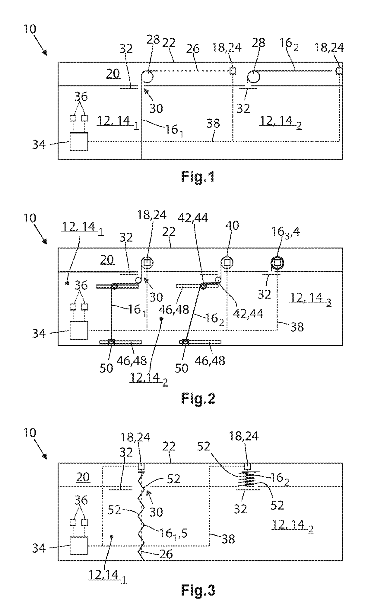
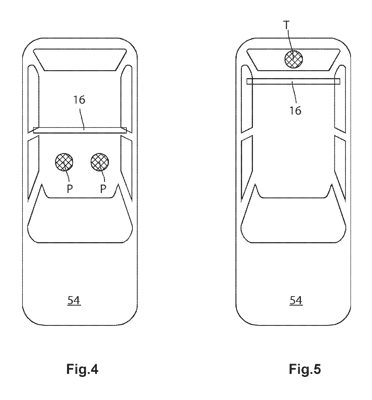
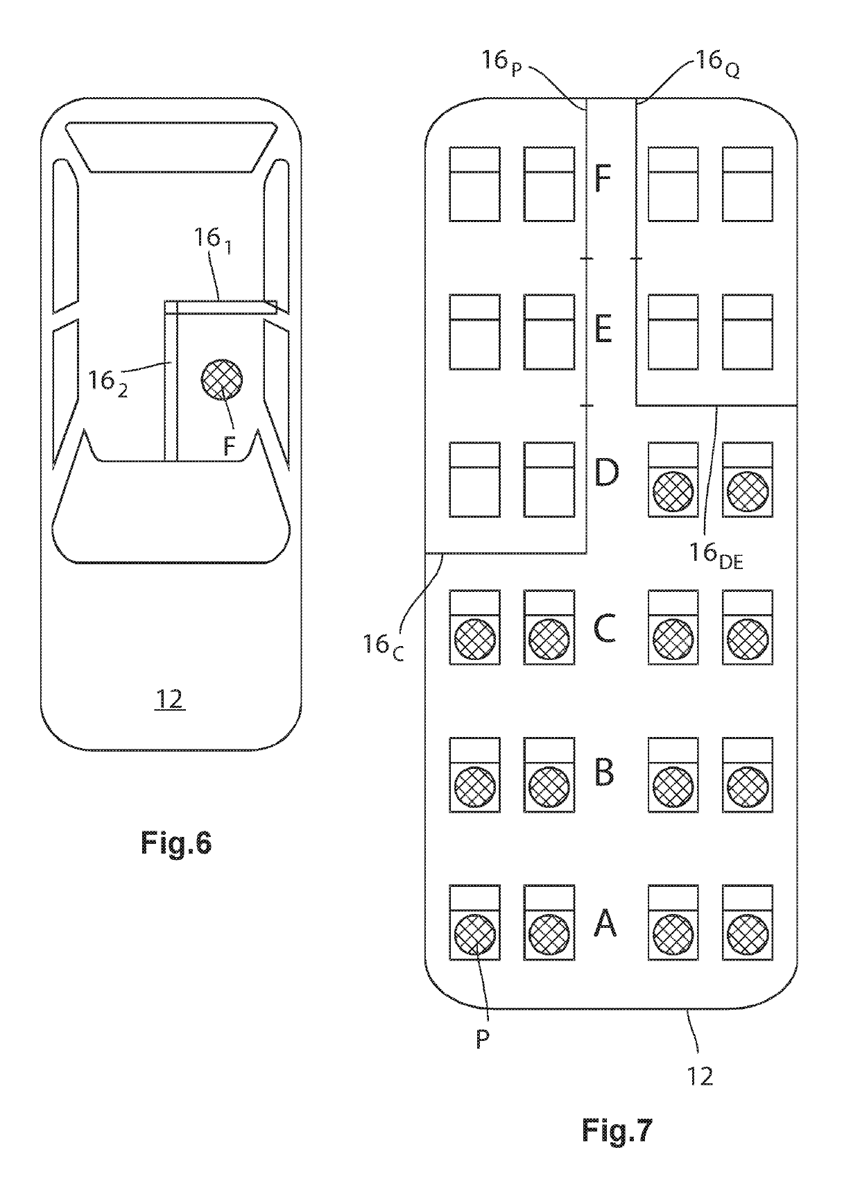
[0017]FIG. 1 is a schematic view of a device 10 according to one embodiment, with which a cab 12 and / or a storage space 12 can be subdivided into a number of sub-portions 14. In the embodiment illustrated, the cab 12 of a vehicle which is not illustrated in greater detail and which may be constructed as an SUV or station wagon is intended to be involved. The term “cab” is usually used for enclosed spaces in which persons can be located while a storage space 12 is used to receive goods, wherein the transition is fluid since goods are also transported in the cab 12. In the case of vehicle configured as SUVs or station wagons, the cab 12 merges seamlessly into the storage space 12 so that a strict separation between the cab 12 and the storage space 12 is not possible. Therefore, there is no illustration of the distinction.

[0018]The device 10 according to one embodiment comprises in this case a deformable first wall 161 and a deformable second wall 162 which are produced from bendable g...

third embodiment

[0023]FIG. 3 is another schematic illustration of the device 10. In this case, the walls 161,162 comprise a foldable glass. The walls 16 are subdivided by folding edges 52 into a corresponding number of segments. Consequently, the walls 16 can be moved similarly to a blind between the open position and the closure position. To this end, the sheathed cable 26 is connected to the free end of the wall 16. If the sheathed cable 26 is pulled by the drive unit 18, the segments of the wall 16 fold together, as is the case in the second wall 162. In order to be able to move the wall 16 from the open position into the closure position, the sheathed cable 26 simply has to be relaxed. In order to ensure that the wall 16 also moves in the direction of the closure position, it may have a weighted piece which is not illustrated and which is fixed to the free end. Alternatively, there may be provided an additional sheathed cable 26 which is also not illustrated and which is guided in such a manner...


PUM


Abstract

A device for subdividing vehicle cabs and / or storage spaces into a number of sub-portions, comprising a number of deformable walls and a drive unit for moving the walls between an open position, in which the walls do not subdivide the cab and / or the storage space, and a closure position, in which the walls subdivide the cab and / or the storage space into the sub-portions. The walls become deformed during movement between the closure position and the open position. Also included is a method for subdividing vehicle cabs and / or storage spaces into a number of sub-portions and a vehicle.

Description

FIELD OF THE INVENTION[0001]The present invention generally relates to a device and method for subdividing vehicle cabs and / or storage spaces into a number of sub-portions, and further relates to a vehicle having such a device which is operated with the method.BACKGROUND OF THE INVENTION[0002]During temperature control of cabs and / or storage spaces of vehicles, aircraft, trains, ships and / or the like, the energy consumption which is caused by the air conditioning units used for this purpose is very high, particularly when the temperature differences between the internal temperature and the external temperature are particularly great. Depending on the load being transported, it may further be necessary also to cool the load down to a relatively low temperature level, which typically results in a high energy consumption, particularly in the case of high external temperatures. In the case of air conditioning systems which are supplied with electricity, as a result of the high energy co...

Claims


Application Information

Patent Timeline
Patent Type & Authority Patents(United States)
IPC IPC(8): B62D33/04B60R21/02B60P3/20B60R5/04
CPCB62D33/042B60R21/026B60R2021/0266B60R5/047B60R5/048B60P3/205B62D33/06
Inventor GUSSEN, UWEARNDT, CHRISTOPHSTEFAN, FREDERICPETRI, FRANK
Owner FORD GLOBAL TECH LLC
Learn More