Electric winch crank

a winch crank and electric technology, applied in the direction of winding mechanisms, hoisting equipment, etc., can solve the problems of maximum stress on the muscles of the body, uncomfortable position, and motorized crank types, and achieve the effect of reducing the mass of the crank and reducing the rotation speed of the input shaft of the mechanical reducer

Active Publication Date: 2019-07-23
CHRYSADEV
View PDF17 Cites 0 Cited by
  • Summary
  • Abstract
  • Description
  • Claims
  • Application Information

AI Technical Summary

Benefits of technology

[0028]In other words, this crank also makes it possible to adjust the rotation speed of the electric motor, directly from the handle, in order to facilitate and improve the performance of frequent maneuvers. Also in this case, the transmission mechanism guarantees optimal instruction transmission to the electronic circuit.
[0030]Thus, when using the electric crank, the pleasure sailor has direct and ergonomic access to the controls thus allowing for a reduction in maneuvering time. The pleasure sailor does not need to release the handle with one hand in order to actuate a button at the opposite end of said crank during a maneuver, which is thus performed in a continuous manner.
[0036]In another embodiment, the mechanical reducer can also be mounted directly in line with the winch coupling means, with the shafts of the mechanical reducer therefore oriented vertically. The bevel gear is interposed between the motor and the reducer in order to connect the output shaft of the horizontally oriented electric motor to the input shaft of the mechanical reducer. With this bevel gear, the rotation speed of the input shaft of the mechanical reducer can also be reduced.
[0037]In a second variant, the output shaft of the motor is arranged vertically compared to the main body of the crank. In this case, the motor, the braking system and the reducer are all mounted in line with the winch coupling means. This particular arrangement makes it possible to reduce the mass of the crank and to concentrate the masses in line with the coupling means of the winch.
[0040]According to a specific embodiment, the battery is mounted at the opposite end of the gripping handle and protrudes in the extension of the main body thus forming a second grip zone. In this way, the operator carries the crank using these two grip zones and thus improves accuracy when coupling / uncoupling it to the capstan of the winch.
[0042]In other words, without other action, the braking system prevents the electric motor from turning due to mechanical friction, such that the crank can be used manually.

Problems solved by technology

However, this type of motorized crank can have some drawbacks.
He often finds himself, arriving at the end of the exertion, in an uncomfortable position for which the stress on the muscles of the body is at a maximum.
Another drawback of this type of crank resides in the absence of a control member with which to progressively adjust / control the rotation speed depending upon the type of maneuver.
The operator must therefore release the handle with one hand in order to work this control, thus losing time and precision, and imposing a greater effort on the operator.
Thus, as previously mentioned, the amateur sailor cannot perform a complete maneuver while keeping both hands on the gripping handle of the crank.
The maneuver cannot therefore be performed in a continuous manner, which in practice is a drawback.

Method used


Image

  • Electric winch crank
  • Electric winch crank
  • Electric winch crank

Examples


first embodiment

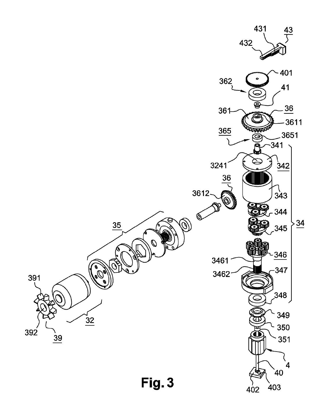
[0068] this ventilation system 39 particularly comprises blades 391 and an opening 392 in which the output shaft of the motor 32 is engaged. When the motor 32 turns, the ventilation system 39 and more particularly the rotation of these blades 391, leads to the evacuation of heat by means of air circulation within the volume of the main body 3. The heat is discharged to the outside through the main body 3 of the crank 1. The heat generated by the electronic circuit 31 can also be evacuated by this ventilation system 39. Because of the presence of a lubrication system 139 on the hollow shaft carrying the bevel gear 36, and the mechanical reducer 34, circulation of the ventilation system must if possible, be avoided within this area of the crank 1.

second embodiment

[0069] the ventilation system is an electric fan which has the advantage of operating independently of the motor, because it is preferably controlled by the electronic circuit 31. Thus, this type of fan makes it possible on the one hand to guarantee the circulation of air within the main body and to do so independently of the rotation speed of the motor. On the other hand, it allows heat to be evacuated even after stopping the motor in such a way as to continuously reduce the temperature within the main body.

[0070]The crank can also comprise a thermal diffusion mechanism embedded within the circulation circuit, with the aim of improving the removal of heat within the main body. According to the application, this thermal diffusion mechanism may comprise a set of fins or a plate made of a metallic material, typically of aluminum molded onto the body of the crank, such as to evacuate the heat captured by the diffusion mechanism into the ventilation flow.

[0071]Means of sealing, not show...


PUM


Abstract

An electric winch crank having a main body which includes an electric motor; a gripping handle arranged at one end of the main body and able to pivot on same with respect to the main body; a coupling means to a winch, arranged at the opposite end of the main body; a transmission mechanism driven by the output shaft of the motor and enables rotation of the coupling means; a mechanical reducer interposed between the output shaft of the motor and the coupling means, the crank further comprising a braking system mounted on the output shaft of the motor; a control member located on the gripping handle for actuating the braking system via the electronic circuit and a rotating collector having a first portion rigidly attached to the gripping handle, connected to the control member, and a second portion rigidly attached to the main body and electrically connected to an electronic circuit.

Description

CROSS REFERENCE TO RELATED APPLICATIONS[0001]This application is a national stage filing under section 371 of International Application No. PCT / FR2016 / 050081, filed on Jan. 20, 2016, and published on Jul. 28, 2016 as WO 2016 / 116685, which claims priority to French National Application No. 1550438, filed on Jan. 20, 2015. The entire contents of each of said applications are hereby incorporated herein by reference.TECHNICAL DOMAIN[0002]The present invention relates to the technical domain of nautical equipment and particularly to accessories used on sailboats. More specifically it concerns an electric winch crank.PRIOR ART[0003]In general, a sailboat has one or more mechanisms referred to as a ‘winch’, i.e., winches around which a rope is wound / unwound in order, in particular, to trim sheets or hoist a sail. There are different types of cranks with which to maneuver these winches and in particular motorized cranks offering the operator the possibility of performing a maneuver either m...

Claims


Application Information

Patent Timeline
Patent Type & Authority Patents(United States)
IPC IPC(8): B66D1/74
CPCB66D1/7478B66D1/7473
Inventor RABU, BRUNO
Owner CHRYSADEV
Why Eureka
Try Eureka