Flexible and steerable elongate instruments with shape control and support elements

Active Publication Date: 2019-07-30
AURIS HEALTH INC
View PDF409 Cites 16 Cited by
  • Summary
  • Abstract
  • Description
  • Claims
  • Application Information

AI Technical Summary

Benefits of technology

[0026]According to another embodiment, a method of shape or articulation control may be provided. The method may include inserting an elongate instrument into a patient through either an incision or orifice, advancing the elongate instrument through a pathway inside the patient, manipulating the elongate instrument to conform or match a shape or curvature of the pathway as the elongate instrument is being advanced through the pathway, controlling the displacement of a flex member along a length of the elongate instrument, altering the stiffness of a first portion of the elongate instrument, changing the radius of curvature of the elongate instrument, and steering the first portion or second portion of the elongate instrument around curvatures of the pathway.
[0027]According to another embodiment, an instrument having a flexible and elongated body includes at least two lumens and a flex member disposed within one of the lumens. The flex member may be capable of providing steering control to a first portion of the elongate body while providing load bearing support to a second por

Problems solved by technology

However, minimally invasive surgical procedures typically require using extension tools to approach and address the target site, and the typical extension tools may be difficult to use, manipulate, and co

Method used


Image

  • Flexible and steerable elongate instruments with shape control and support elements
  • Flexible and steerable elongate instruments with shape control and support elements
  • Flexible and steerable elongate instruments with shape control and support elements

Examples


Example

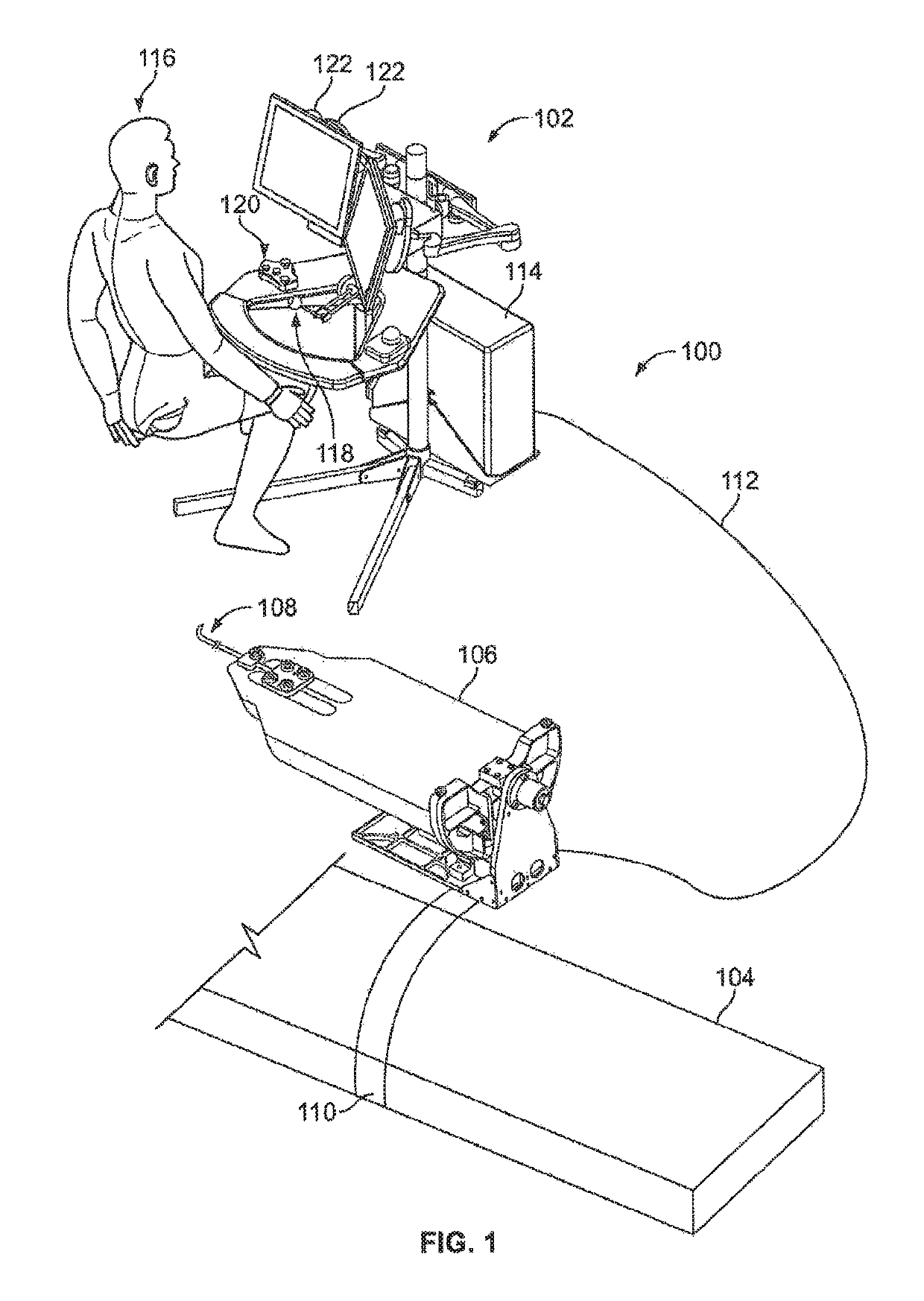
[0055]Reference will now be made in detail to the preferred embodiments of the present invention, examples of which are illustrated in the accompanying drawings. While the invention will be described in conjunction with the preferred embodiments, it will be understood that they are not intended to limit the scope of the invention to these embodiments. On the contrary, the invention is intended to cover alternatives, modifications, and equivalents that may be included within the spirit and scope of the invention. Furthermore, in the following detailed description of the present invention, numerous specific details are set forth in to order to provide a thorough understanding of the present invention. However, it will be readily apparent to one of ordinary skilled in the art that the present invention may be practiced without these specific details.

[0056]The contents of the following applications are incorporated herein by reference as though set forth in full for all purposes: U.S. p...


PUM


Abstract

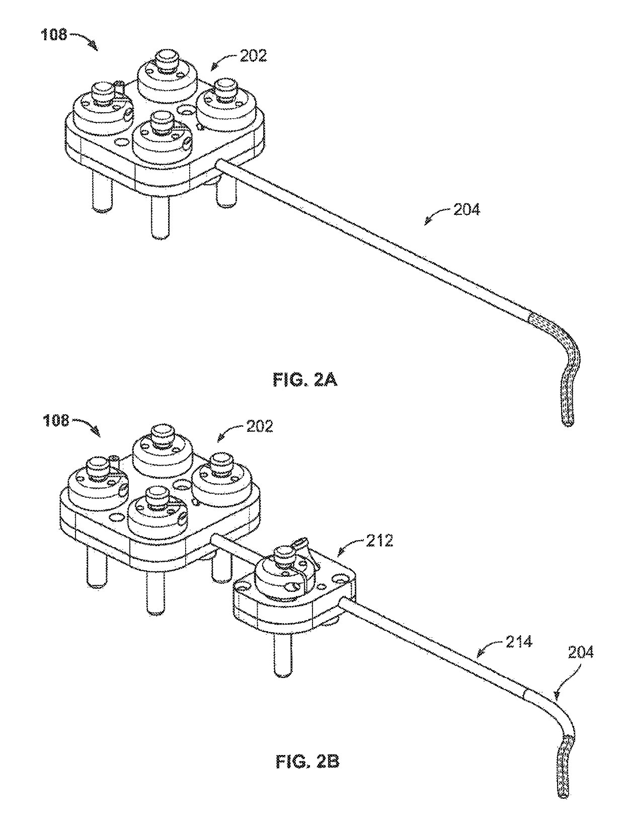
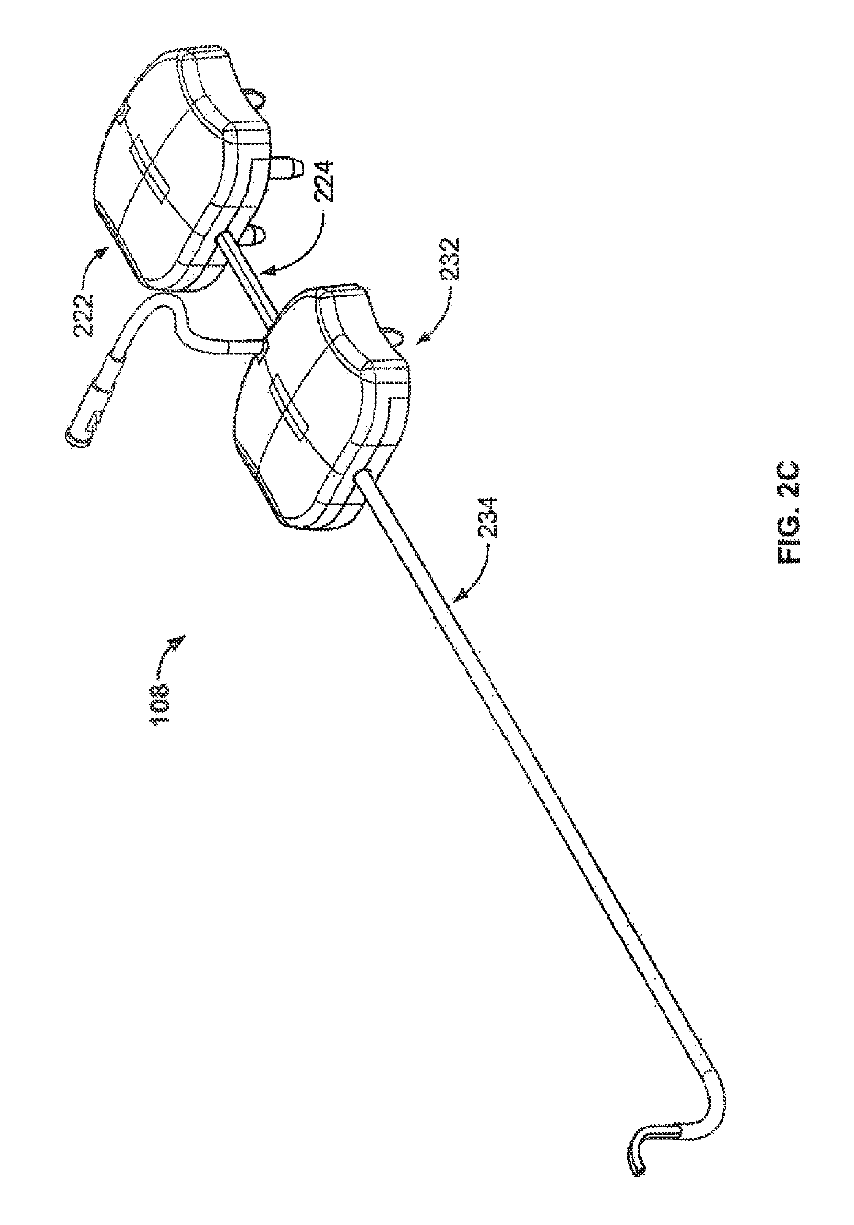
An instrument having a flexible and elongated body includes at least a lumen and a flex member disposed within the lumen. The flex member may be capable of providing steering control to a first portion of the elongate body while providing load bearing support to a second portion of the elongate body. A pull wire may be disposed within the flex member, and at least a distal portion of the pull wire may be coupled to the elongate body and a proximal portion of the pull wire may be operatively coupled to a control unit. The control unit may be coupled to a proximal portion of the elongate body. In addition, a control member may be operatively coupled to the control unit such that a distal portion of the control member may be positioned near a proximal portion of the flex member. The control member may be configured to support the flex member and control the movement or displacement of the flex member. Furthermore, the flex member may be configured to selectively decouple articulation or steering forces of a first portion of the elongate body away from a second portion of the elongate body; thereby, preventing compression of the second portion of the elongate body while maintaining elasticity or flexibility of the second portion of the elongate body.

Description

CROSS-REFERENCE TO RELATED APPLICATION[0001]This application is a continuation of U.S. patent application Ser. No. 12 / 432,683, filed Apr. 29, 2009, entitled “FLEXIBLE AND STEERABLE ELONGATE INSTRUMENTS WITH SHAPE CONTROL AND SUPPORT ELEMENTS,” the entirety of which is herein incorporated by reference.FIELD OF INVENTION[0002]The present invention relates generally to robotically controlled systems, such as robotic or telerobotic surgical systems, and more particularly to flexible and steerable elongate instruments or catheters with adjustable or changeable shape and articulation control for performing minimally invasive surgical operations.BACKGROUND[0003]Standard surgical procedures or open surgeries typically involve using a scalpel to create an opening of sufficient size to allow a surgical team to gain access to an area in the body of a patient for the surgical team to diagnose and treat one or more target sites. When possible, minimally invasive surgical procedures may be used i...

Claims


Application Information

Patent Timeline
IPC IPC(8): A61B1/00A61M25/01A61B34/30A61B17/00A61B1/005A61B34/00
CPCA61B34/30A61B1/0055A61B1/0057A61B1/00078A61B17/00234A61B34/71A61M25/0136A61M25/0138A61M25/0144A61M25/0147A61B2017/00318A61B2017/00327A61B2034/301A61B2034/303A61M2025/015A61M2025/0161A61B2017/00017A61B2017/00305A61M25/02A61M2025/0293
Inventor ALVAREZ, JEFFERY B.ROMO, ENRIQUEMACNAMARA, FRANCIS
Owner AURIS HEALTH INC
Why Eureka
Try Eureka