Photon counting device and method

a technology of counting device and photon, which is applied in the field of photon counting device, can solve the problems of degrading spectral performance and contaminated expected spectrum by false low energy, and achieve the effect of avoiding problems, drawbacks and/or shortcomings of the prior art, or at least reducing or reducing

Active Publication Date: 2019-07-30
KONINKLJIJKE PHILIPS NV
View PDF9 Cites 5 Cited by
  • Summary
  • Abstract
  • Description
  • Claims
  • Application Information

AI Technical Summary

Benefits of technology

[0012]It is an object of the present invention to provide a photon counting device and a photon counting method which allow to account for charge sharing and in which the problems, drawbacks and / or shortcomings of the prior art are avoided or at least reduced or mitigated.
[0014]In a second aspect of the present invention, a photon counting method for counting photon interactions in a piece of converter material is presented, comprising the steps of receiving a pulse generated by a photon interacting with the piece of converter material, providing a pulse logic signal upon the pulse reaching a predetermined energy level, and preventing, in case a neighboring logic signal indicating an input of predetermined energy level in at least one neighboring piece of converter material and the pulse logic signal are present together in a coincidence window of predetermined size, the pulse from being counted by any one of a plurality of counters, each of the counters being coupled to one of a plurality energy discriminators, for counting photon interactions with energy discrimination according to an energy level of the coupled energy discriminator, each energy discriminators being arranged to receive the pulse.
[0016]The width of the coincidence window is preferably selected such that the probability of rejecting true events is low. Due to the high rates in CT applications, there is a finite probability that two adjacent pixels receive impinging photons near-simultaneously. A too large window would cause the circuit to reject too many events that may not have been caused by charge sharing. If, however, the invention is used in a context where there is a lower rate, the coincidence window may be broader. Furthermore, it is contemplated that the size of the coincidence window may be dynamic in a sense that, for example, depending on the photon flux in a previous time frame for a pixel or group of pixels, the coincidence windows of such pixel or group pixels is adjusted. This means that during a period of high flux for a pixel or group of pixels, the coincidence window may be or become smaller, while during a period of low flux, the coincidence window may be or become broader. A dynamic adjustment of the coincidence window (either generally or separately on a basis per pixel or per group of pixels) is expected to allow for better compromising for the rejection of charge sharing versus the rejection of true coincidences over a larger dynamic range.
[0040]By providing the pulse, potentially, also to a neighboring photon counting device, a greater flexibility and accuracy as to the assigning to the charge sharing event to a particular pixel may be obtained.

Problems solved by technology

One of the challenges in photon counting is the so-called charge sharing.
In particular, charge sharing in direct-conversion materials causes a degradation of the spectral performance.
Effectively this means that the expected spectrum is contaminated by false low energy events which no longer contribute to the photo-peak but rather show up as a background signal generally referred to as “low energy tail”.

Method used


Image

  • Photon counting device and method
  • Photon counting device and method
  • Photon counting device and method

Examples


Embodiment Construction

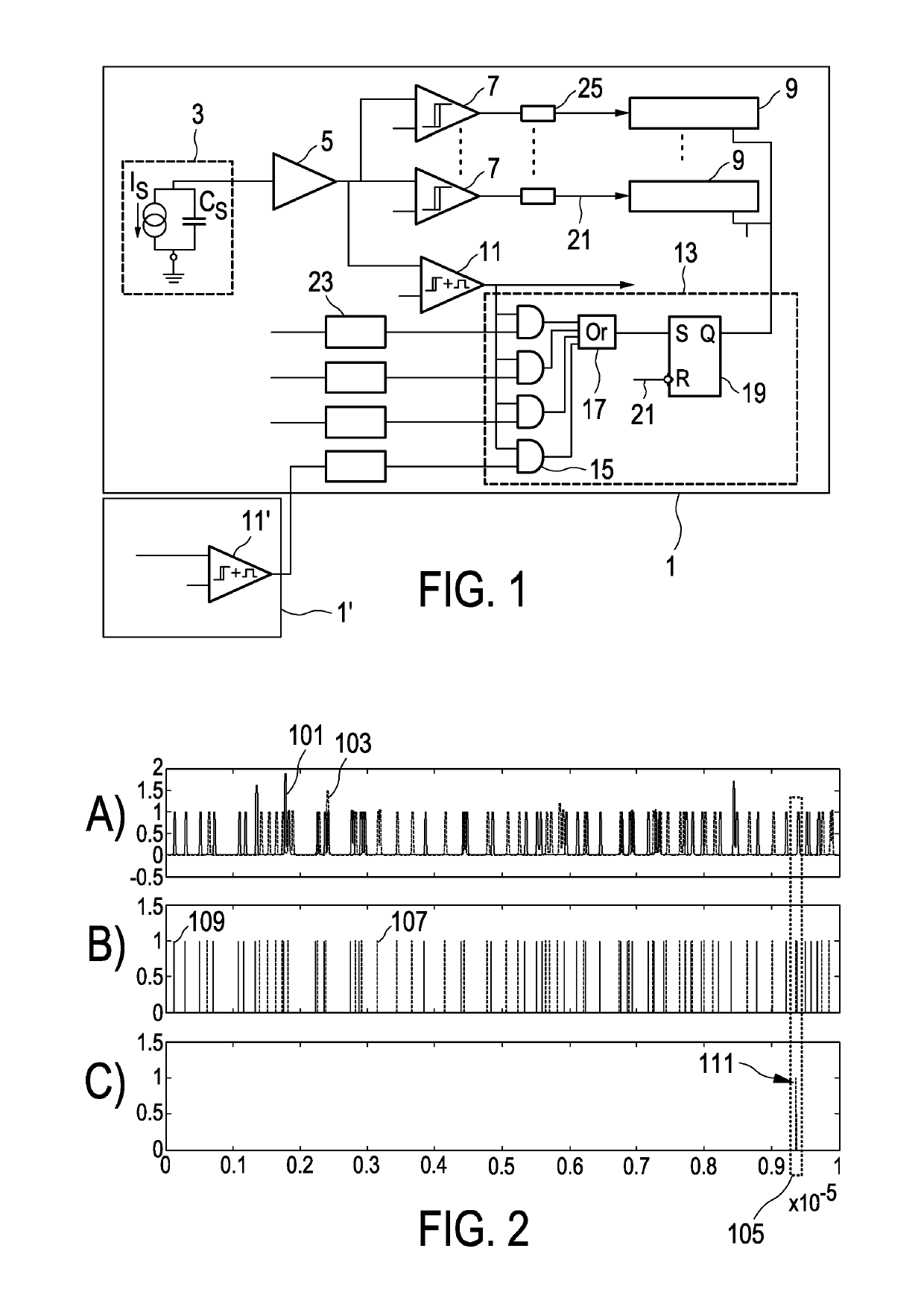
[0056]FIG. 1 shows a block diagram illustrating a photon counting device in accordance with an embodiment of the invention.

[0057]The photon counting device 1 in this embodiment includes a direct converter 3, providing its output to a pulse shaper 5, which in turn provides the shaped pulse to a number of energy discriminators 7 (or threshold sections). For each of these threshold sections 7 a corresponding counter 9 is provided.

[0058]The basic outline of the photon counting device 1 corresponds to conventional photon counting devices, with which the skilled person is well familiar. Accordingly, no additional explanation to the basic operation of these elements needs to be given.

[0059]The term “pixel” is used here, depending on the context, as either referring to the particular piece of converter material or to the combination of such “pixel” with its corresponding photon counting device.

[0060]As indicated above, each pixel includes a typical photon counting channel with several energ...


PUM


Abstract

The invention relates a photon counting device and method for counting photon interactions in a piece of converter material and addressing the issue of charge sharing. The occurrence of a charge sharing event is already detected upon the onset of the pulse, taking into consideration an onset of a pulse in a neighboring pixel within a preferably very short coincidence window. According to the invention, it is detected whether a pulse is being processed and one or more neighboring pixels are scouted to decide whether a simultaneous interaction has been registered within a very short coincidence window.

Description

CROSS REFERENCE TO RELATED APPLICATIONS[0001]This application is the U.S. National Phase application under 35 U.S.C. § 371 of International Application No. PCT / EP2016 / 068131, filed Jul. 29, 2016, published as WO 2017 / 032548 on Mar. 2, 2017, which claims the benefit of European Patent Application No. 15182717.7 filed Aug. 27, 2015. These applications are hereby incorporated by reference herein.FIELD OF THE INVENTION[0002]The invention relates to a photon counting device for counting photon interactions in a piece of converter material, a photon counting method for counting photon interactions in a piece of converter material and a corresponding software product.BACKGROUND OF THE INVENTION[0003]Photon counting may be employed in a number of contexts, one of which is medical imaging. For example, energy resolving photon counting detectors are used for spectral computer tomography (CT). Somewhat similar detectors are provided also in other applications, e.g. photon-counting mammography....

Claims


Application Information

Patent Timeline
Patent Type & Authority Patents(United States)
IPC IPC(8): G01T1/00G01T1/29G01T1/17G01T1/24H04N5/345G01J1/44
CPCG01T1/17G01T1/247H04N5/3456G01T1/2928G01J2001/442H04N25/445
Inventor STEADMAN BOOKER, ROGERROESSL, EWALD
Owner KONINKLJIJKE PHILIPS NV
Why Eureka
Try Eureka