
Bus protocol for dynamic lighting application

a dynamic lighting and bus protocol technology, applied in data switching networks, instruments, transportation and packaging, etc., can solve the problems of complex lighting system setup, limited number of leds that can be controlled, electrical noise in automotive environments, etc., and achieve the effect of robust transmission of instructions

Active Publication Date: 2019-07-30
MELEXIS TECH NV
View PDF5 Cites 3 Cited by
  • Summary
  • Abstract
  • Description
  • Claims
  • Application Information

AI Technical Summary

Benefits of technology

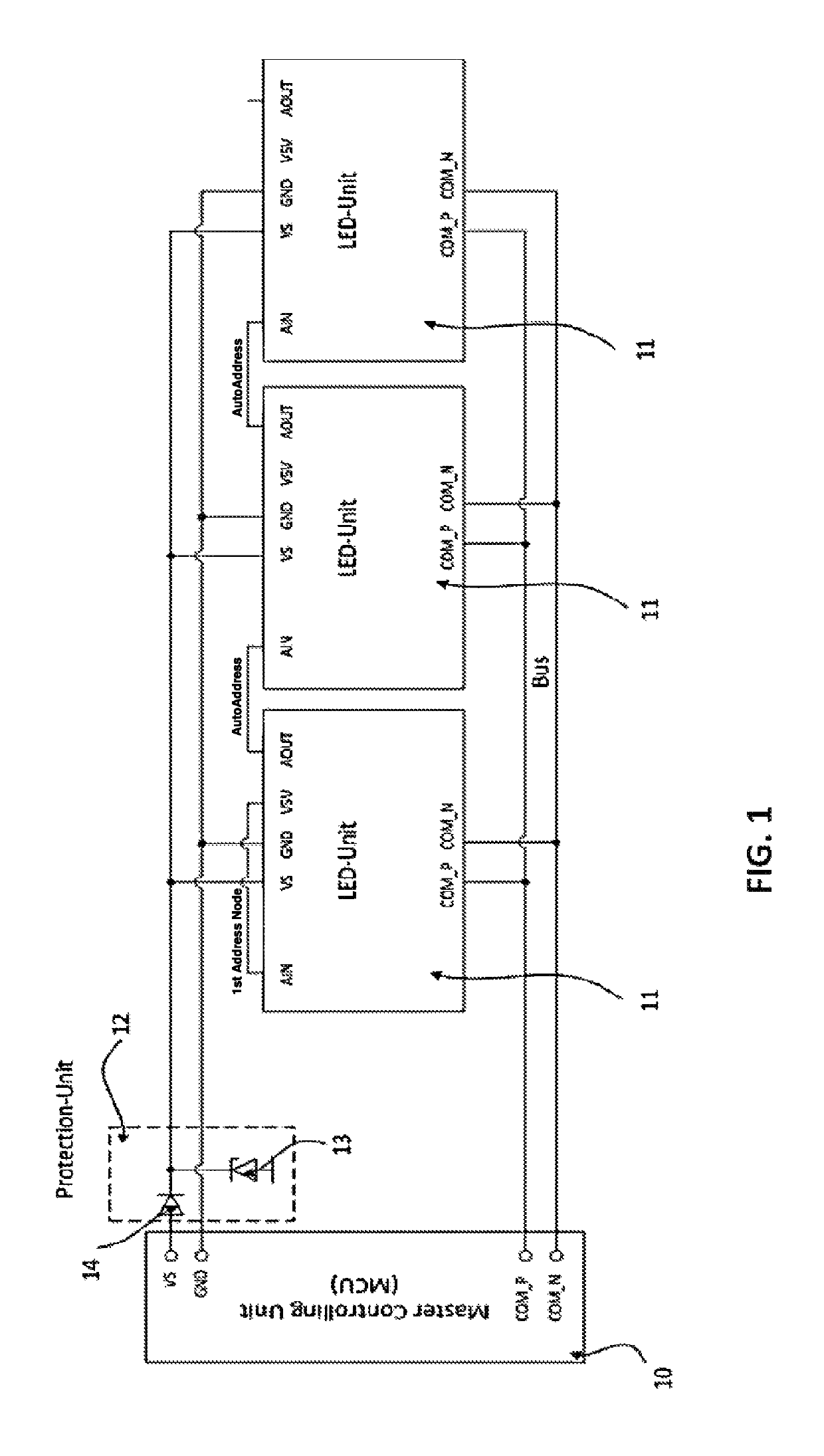
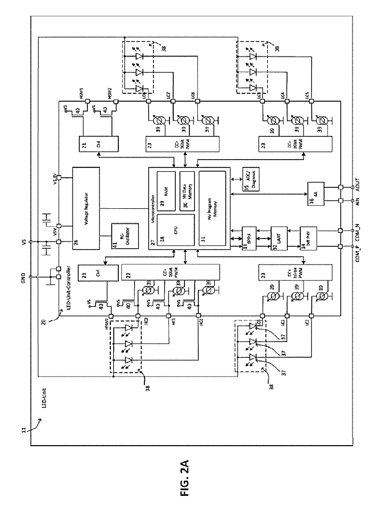
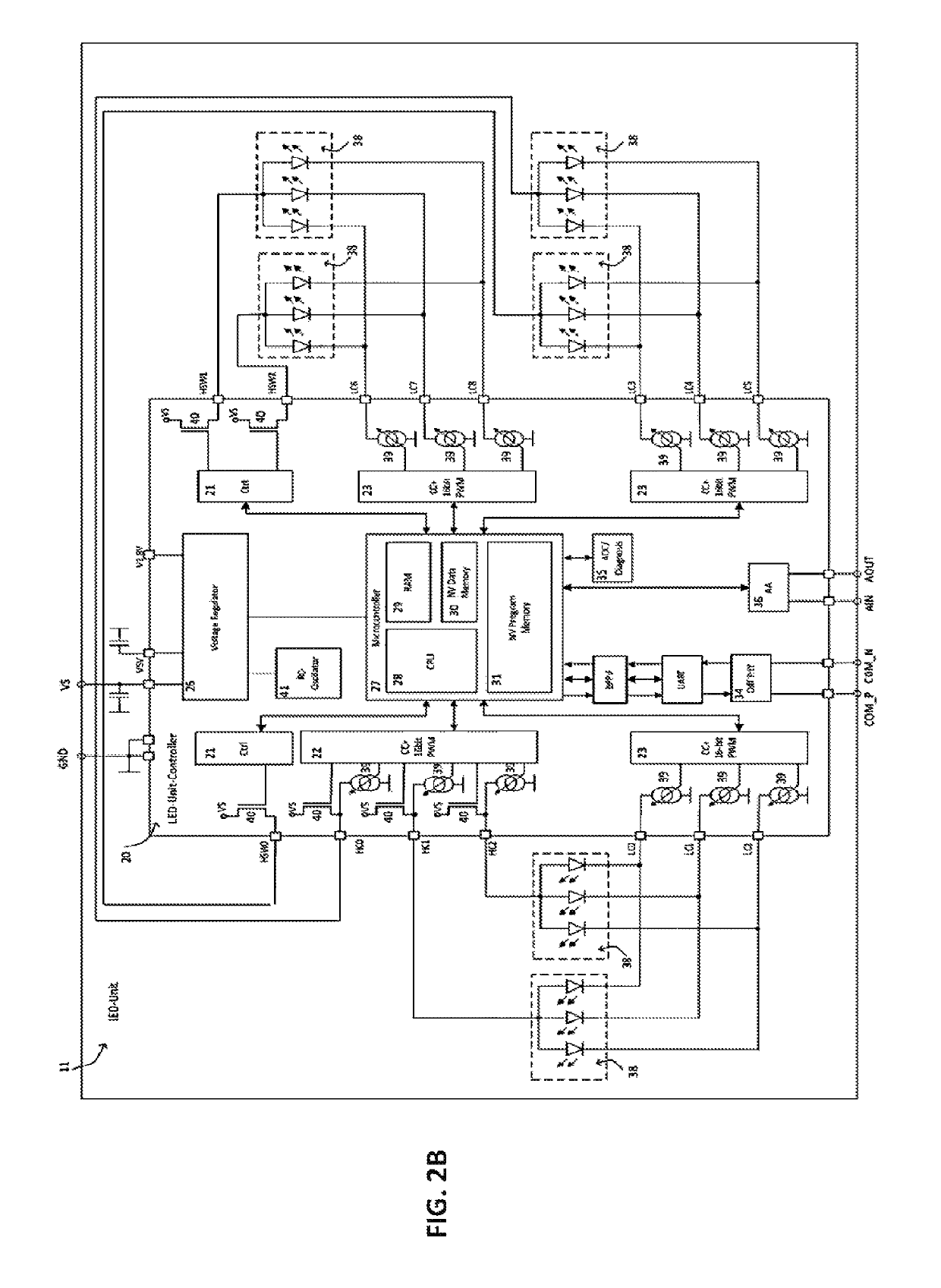
[0006]It is an object of embodiments of the present invention to provide a system for illumination, a bus protocol and an auto-addressing method, which provide a flexible communication network for robust transmission of instructions for powering electronic devices. It is an advantage of embodiments of the present invention that also a flexible communication network is obtained for transmission of diagnostics information, including checking that the data transmission did not contain unwanted changes at one or more stages of the data transmission.

Problems solved by technology

However, automotive environments are electrically noisy.
The number of LEDs that can be controlled is quite limited in case of LIN.
On the other hand, setting illumination systems directly in CAN is complex, difficult to repair or interchange in case of failure or accident, and the implementation is expensive.
Moreover, the existing implementations are prone to errors due to for example interference, electrostatic discharge or antenna effects.
However, this protection is only partial, and it does not allow protection due to variations or irregularities in the LED controllers.

Method used


Image

  • Bus protocol for dynamic lighting application
  • Bus protocol for dynamic lighting application
  • Bus protocol for dynamic lighting application

Examples


Embodiment Construction

[0089]The present invention will be described with respect to particular embodiments and with reference to certain drawings but the invention is not limited thereto but only by the claims. The drawings described are only schematic and are non-limiting. In the drawings, the size of some of the elements may be exaggerated and not drawn on scale for illustrative purposes. The dimensions and the relative dimensions do not correspond to actual reductions to practice of the invention.

[0090]Furthermore, the terms first, second and the like in the description and in the claims, are used for distinguishing between similar elements and not necessarily for describing a sequence, either temporally, spatially, in ranking or in any other manner. It is to be understood that the terms so used are interchangeable under appropriate circumstances and that the embodiments of the invention described herein are capable of operation in other sequences than described or illustrated herein.

[0091]Moreover, t...


PUM


Abstract

A method of operating a plurality of driving units for powering electronic units comprises interchanging a data frame including a bit sequence, between a master control unit and at least one of a plurality of driving units at slave nodes. A step of applying an ID field comprises indicating the driving unit address using a first bit sub-string comprising N bits, allowing the master control unit to identify whether data should be received or transmitted, or allowing each addressed driving unit to decode which action is required by the master control unit, using an R / T command bit, performing a length decoding step, for including information in the ID field regarding the type of instructions included in the data frame, using an F function bit, and assigning data bits to different electronic units or indicating in the length of the bit string in the data field, using a second bit sub-string.

Description

FIELD OF THE INVENTION[0001]The invention relates to the field of illumination and signalization systems. More specifically it relates to control of LED clusters via data transmission.BACKGROUND OF THE INVENTION[0002]Illumination systems, amongst others those for light applications in cars, often make use of LED technology. LED technology typically advantageously is used since the production of LED illumination sources is inexpensive and the energy consumption of LED illumination sources is low.[0003]Control of illumination systems in automotive applications should be robust and fail-proof. For example, it should not be affected by external fields, electric peaks or other sources of noise. However, automotive environments are electrically noisy. A faulty transmission of data, or unintended activation of illumination systems, can result in dangerous situations which should be avoided.[0004]Existing systems typically provide connection between different LEDs and their controllers by L...

Claims


Application Information

Patent Timeline
Patent Type & Authority Patents(United States)
IPC IPC(8): H05B33/08H05B37/02B60R16/02B60Q1/00H04L29/08B60R16/023H04L12/40H05B44/00
CPCH05B37/0254H05B33/0842H04L2012/40273B60R16/0238H04L67/12B60Q1/00H05B45/325H05B47/18G06F13/38H04L1/004H05B45/00
Inventor STURM, JORGENFREITAG, THOMASFROST, RAIKBENDER, MICHAEL
Owner MELEXIS TECH NV
Learn More