Rapid stirring machine

a technology of stirring machine and stirring chamber, which is applied in the direction of mixing, rotary stirring mixer, transportation and packaging, etc., can solve the problems of thickener, and dewatering of dewatering machin

Active Publication Date: 2019-08-06
KUBOTA CORP
View PDF17 Cites 0 Cited by
  • Summary
  • Abstract
  • Description
  • Claims
  • Application Information

AI Technical Summary

Benefits of technology

[0021]As described above, according to the present invention, the rotation of the drive shaft rotates the edged turbine blade in the tank so as to stir sludge and the flocculant in the tank. At this point, the flocculant supplied into the tank is retained in massive form in sludge. The turbine blades cut flocculant lumps so as to disperse the flocculant into fine particles by shearing. This rapidly generates large quantities of flocculated floc forming nucleus, that is, a nucleus for forming flocculated flocs in sludge.
[0022]Thus, in a predetermined residence time of the flocculant and sludge in the tank, solid particles are brought into contact with flocculated floc forming nucleus in sludge with a sufficient frequency, generating large quantities of fine flocs.
[0023]In the rapid stirring machine, fine and uniform flocs are stably generated and then are flocculated in the slow stirring machine. Thus, the flocs can be stably generated in a predetermined size suitable for dewatering.

Problems solved by technology

At this point, without rapidly and sufficiently dispersing the flocculant, fine flocs are insufficiently formed so as to inhibit the formation of flocculated flocs during a slow stir, leading to degradation of dewatering of a dewatering machine, a thickener, and the like in the subsequent steps.

Method used


Image

  • Rapid stirring machine
  • Rapid stirring machine
  • Rapid stirring machine

Examples


Embodiment Construction

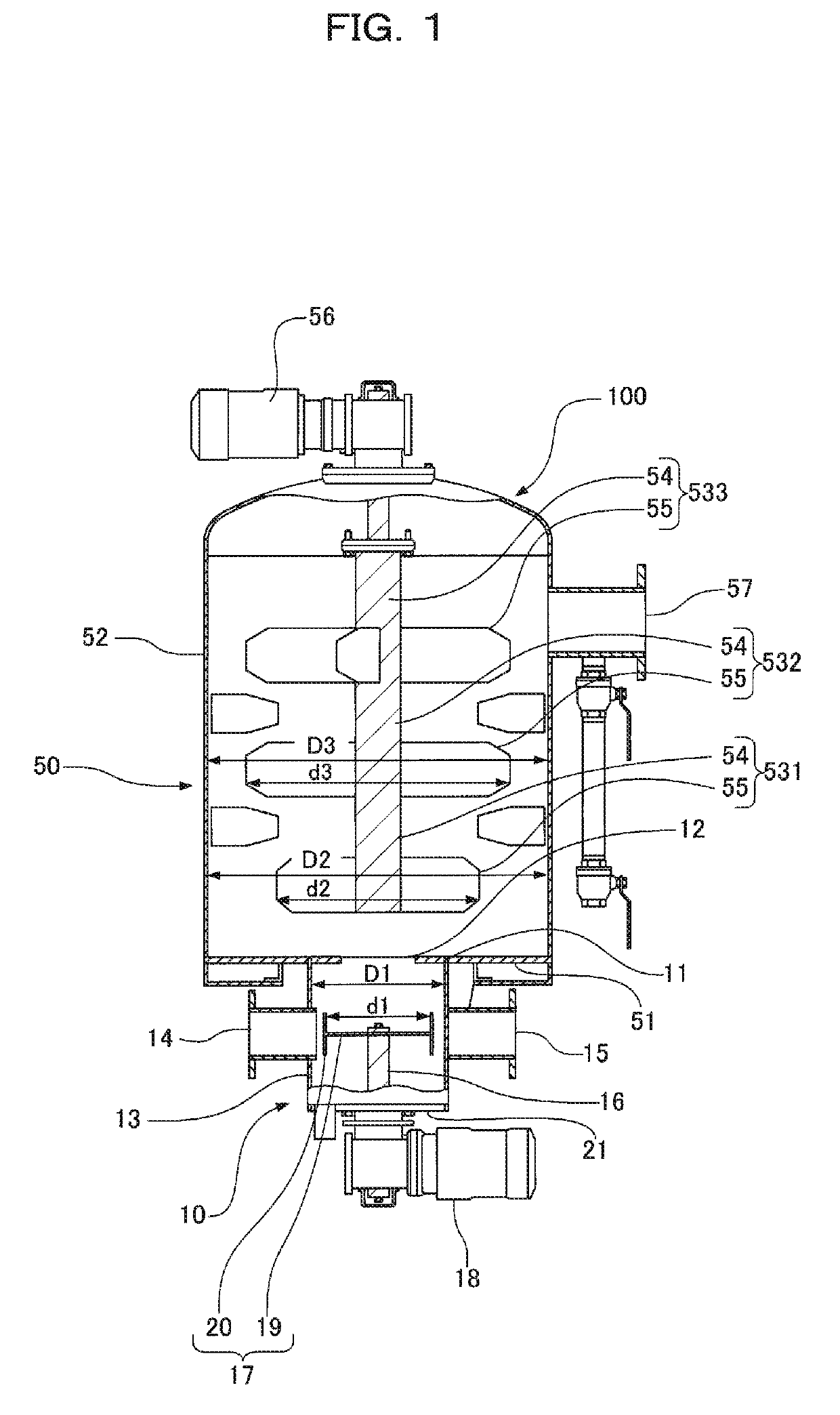
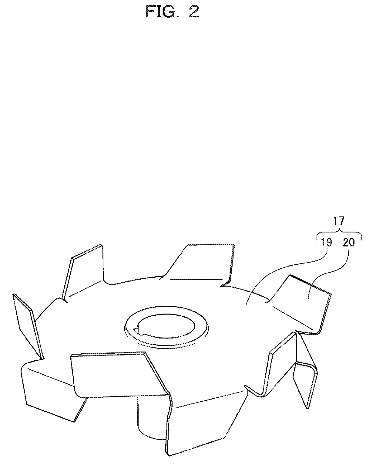
[0038]Embodiments of the present invention will be described below in accordance with the accompanying drawings. The present embodiment is merely exemplary and does not limit the present invention. In FIGS. 1 and 2, a flocculating-mixing apparatus 100 includes a rapid stirring machine 10 and a slow stirring machine 50. The slow stirring machine 50 is disposed on the rapid stirring machine 10. A tank ceiling 11 of the rapid stirring machine 10 and a tank bottom 51 of the slow stirring machine 50 communicate with each other at an opening 12.

[0039]The rapid stirring machine 10 includes a rapid stirring tank 13 for stirring sludge and a flocculant. The opening 12 allowing communication between the rapid stirring machine 10 and the slow stirring machine 50 has a smaller diameter than the inside diameter of the rapid stirring tank 13. The tank ceiling 11 is disposed like a annular shape around the opening 12.

[0040]In the present embodiment, sludge is a slurry material, e.g., sewage sludge...


PUM

PropertyMeasurementUnit
diameteraaaaaaaaaa
shaft poweraaaaaaaaaa

Abstract

A rapid stirring machine including a tank for stirring sludge and a flocculant; a drive shaft disposed in the tank; and an edged turbine blade attached to the drive shaft, the edged turbine blade including turbine blades that are disposed along a virtual circle centered around the axis of the drive shaft, on at least one of the front and back sides of the edged turbine blade in the axial direction of the drive shaft, the turbine blades being raised in the axial direction of the drive shaft.

Description

TECHNICAL FIELD[0001]The present invention relates to a technique of flocculation and mixing in a water-treatment facility or the like and relates to a rapid stirring machine that rapidly stirs and mixes a flocculant and raw water.BACKGROUND ART[0002]A flocculating-mixing tank of the related art is, for example, described in Japanese Patent No. 4761216 (Patent Literature 1). In the flocculating-mixing tank, stirring blades are vertically arranged in two stages and an upward flow of slurry containing a flocculant is supplied to be stirred and mixed. The flocculating-mixing tank is divided into a lower rapid stirring unit and an upper slow stirring unit. The rapid stirring unit has a body inside diameter smaller than that of the slow stirring unit.[0003]The rapid stirring unit has a rapid stirring blade and a drive shaft that drives the rapid stirring blade. The rapid stirring blade includes one turbine blade that has a plurality of wings radially disposed on a surface of a rotating p...

Claims


Application Information

Patent Timeline
Patent Type & Authority Patents(United States)
IPC IPC(8): B01F3/12C02F11/12C02F1/52B01F7/22B01F7/18B01F7/16C02F11/14B01F7/00B01F27/91C02F11/147
CPCB01F7/167B01F3/1221B01F7/0025B01F7/162B01F7/166B01F7/169B01F7/183B01F7/22C02F1/5281C02F11/14B01F7/18C02F11/12B01F2215/0052B01F2215/0431C02F11/147B01F23/53B01F27/84B01F27/87B01F27/902B01F27/91B01F27/90B01F27/112B01F27/808B01F27/851B01F2101/305
Inventor TAKAHASHI, KOJITAMURA, TAKASHIHIGASHI, RYUJI
Owner KUBOTA CORP
Why Eureka
Try Eureka