Motor vehicle chassis

Active Publication Date: 2019-08-06
HOERBIGER AUTOMOTIVE KOMFORTSYST
View PDF27 Cites 2 Cited by
  • Summary
  • Abstract
  • Description
  • Claims
  • Application Information

AI Technical Summary

Benefits of technology

[0019]In a preferred improvement, the adapter comprises a base member and an actuating portion, which is guided displaceably thereon and is provided with the spring seat already mentioned hereinabove. Preferably this (annular) hydraulic working chamber —and if applicable also the (annular) hydraulic-fluid storage container—is constructed between a housing portion of the base member and the actuating portion of the adapter in a manner integrated therein. The housing portion, which particularly preferably is joined to the basic structure of the motor vehicle body, is then able, quite particularly preferably, to enclose an adapter core, on the outer circumferential surface of which, i.e. in the separating face between the adapter core and a jacket region of the housing portion surrounding this, hydraulic fluid ducts are constructed. Such an arrangement of fluid ducts (on the upstream side and/or downstream side) permits construction of the pump unit with minimum possible dimensions, which favors disposing the hydraulic pump of the hydraulic aggregate also in the space enclosed by the coil spring.
[0020]The adapter core is preferably cylindrically constructed and fixed sealingly in a corresponding cylindrical cavity of the housing

Problems solved by technology

And the operating properties of the system benefit from the possibility of particularly short hydraulic lines (due to high stiffness and res

Method used


Image

  • Motor vehicle chassis
  • Motor vehicle chassis

Examples


Example

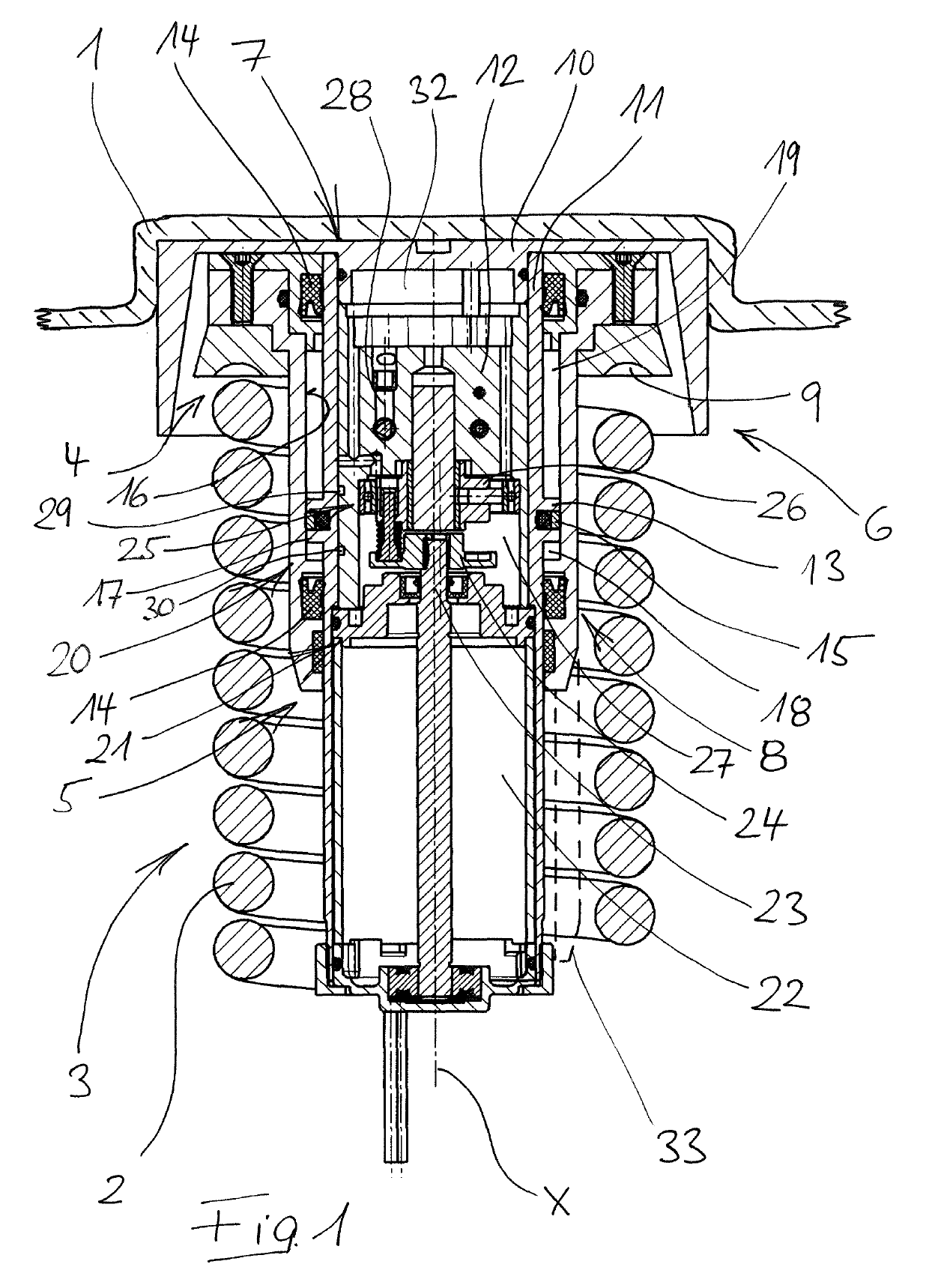
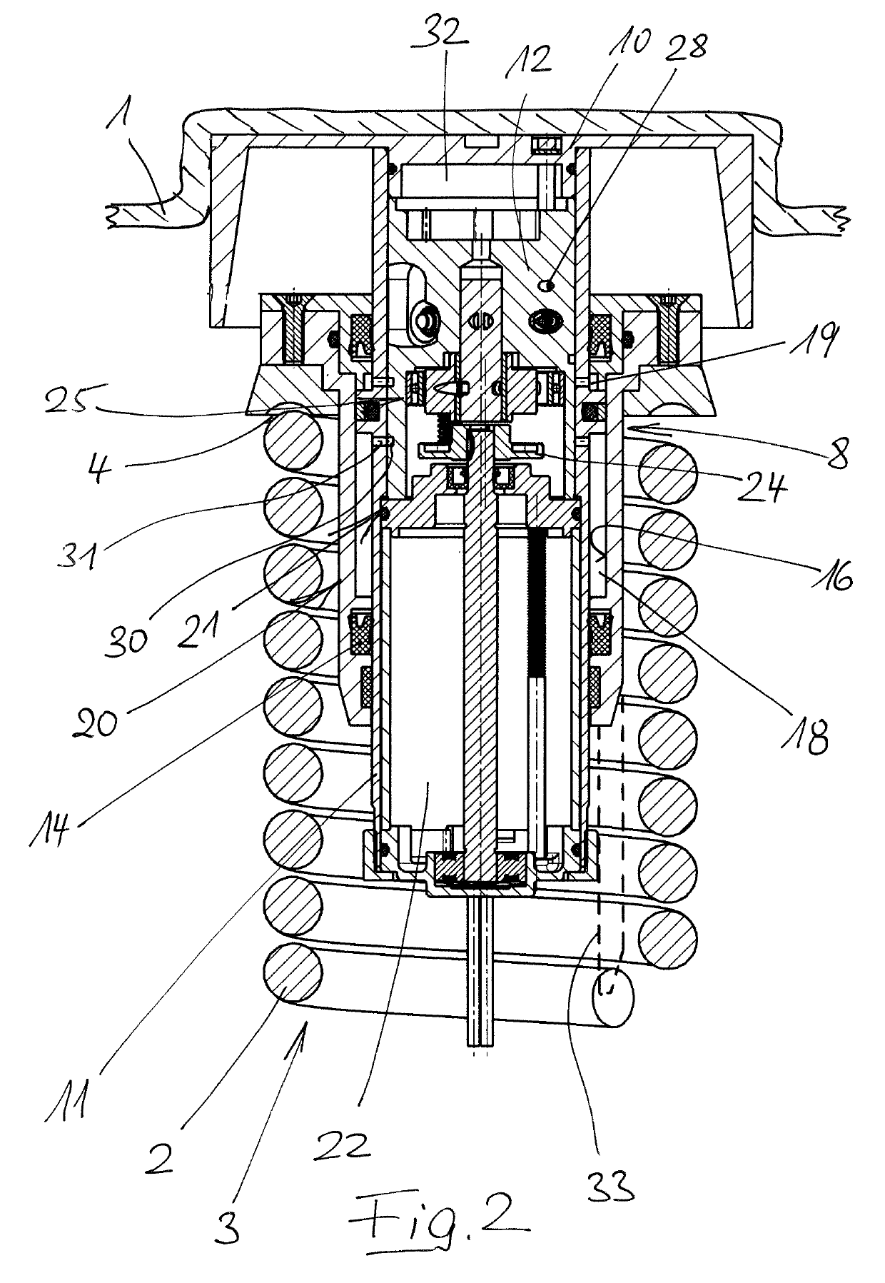
[0025]The height-positioning device illustrated in the drawing is part of a motor vehicle chassis, which corresponds as such to the generally known prior art (and therefore is not shown), and which comprises a basic structure 1 and several wheels connected thereto via one wheel suspension each. At least that wheel suspension with which the wheel suspension shown in the drawing is associated is provided with a spring 3, constructed as a coil spring 2, and a shock absorber (not shown), disposed outside spring 3.

[0026]The shown hydraulic height-positioning device acts in such a way on upper foot point 4 of coil spring 2 that the distance from upper foot point 4 of coil spring 2 to basic structure 1 of the motor vehicle chassis is variable. For this purpose, the hydraulic height-positioning device is constructed as a complex positioning assembly 5. This comprises an adapter 6, which in turn comprises in particular a base member 7 and an actuating portion 8 guided displaceably thereon. W...


PUM


Abstract

In a motor vehicle chassis, at least one wheel suspension, which comprises a spring in the form of a coil spring, has associated therewith a hydraulic height adjustment device having a cylinder-piston arrangement which acts on a base point of the coil spring. The cylinder-piston arrangement can be supplied by a decentral hydraulic aggregate which is associated with the relevant wheel and comprises a storage container for hydraulic fluid and a hydraulic pump driven by an electric motor. At least the electric motor of the hydraulic aggregate is situated within the coil spring.

Description

CROSS REFERENCE TO RELATED APPLICATIONS[0001]This application is a continuation under 35 U.S.C. § 120 of International Application PCT / EP2016 / 077146, filed Nov. 9, 2016, which claims priority to German Application No. 10 2015 119 637.9, filed Nov. 13, 2015, the contents of each of which are incorporated by reference herein.FIELD OF THE INVENTION[0002]The present invention relates to a motor vehicle chassis comprising a basic structure and several wheels connected thereto via one wheel suspension each.BACKGROUND[0003]In motor vehicle chassis, the wheel suspensions, via which the wheels are connected to the basic structure, are usually a spring as well as a shock absorber. In this context, different possibilities are known as regards the construction of the spring (coil springs, leaf springs, torsion springs) as well as its spatial arrangement relative to the other components of the wheel suspension, especially relative to the associated shock absorber. A variant that is widely used, ...

Claims


Application Information

Patent Timeline
IPC IPC(8): B60G17/027B60G15/06B60G15/02B60G17/015
CPCB60G17/0272B60G15/02B60G15/06B60G17/0152B60G2500/30B60G2202/30B60G2202/32B60G2202/413B60G2202/12B60G2204/124
Inventor STOLLE, KLAUSHUBER, GERHARDSCHLEICH, GISELAOSTERRIED, JURGENMULLER, PETER
Owner HOERBIGER AUTOMOTIVE KOMFORTSYST
Why Eureka
Try Eureka