Method for detecting a malfunction of a sensor of a vehicle safety device

Active Publication Date: 2017-09-21
TRW AUTOMOTIVE GMBH
View PDF2 Cites 0 Cited by
  • Summary
  • Abstract
  • Description
  • Claims
  • Application Information

AI Technical Summary

Benefits of technology

The patent text describes a method for detecting malfunctions or defects of sensors used in vehicle safety devices, such as airbags and vehicle dynamics control systems. The method is adapted based on the specific driving situations of the vehicle, reducing the number of false reports and detecting true errors more quickly and reliably. The technical effect of this invention is to increase the operating safety of airbag systems and vehicle dynamics control systems.

Problems solved by technology

If false measuring values are not detected or a defect-free sensor is classified as being defective, the vehicle safety devices may operate in an erroneous or suboptimum manner.
However, the malfunction detection of these self-testing sensors is not precise enough in some conditions.

Method used


Image

  • Method for detecting a malfunction of a sensor of a vehicle safety device
  • Method for detecting a malfunction of a sensor of a vehicle safety device
  • Method for detecting a malfunction of a sensor of a vehicle safety device

Examples


Embodiment Construction

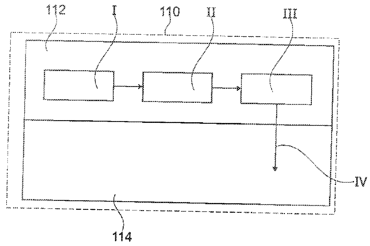
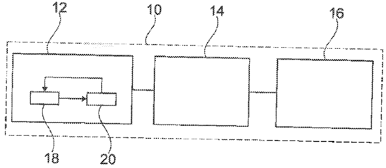
[0032]FIG. 2 schematically illustrates a vehicle safety device 10 which includes a self-testing sensor 12, a control unit 14 and a safety component 16.

[0033]The vehicle safety device 10 is, for example, an airbag system or vehicle dynamic control, also referred to as ESP, ESC etc. In that case, the safety component 16 is, for example, an airbag or a brake accordingly.

[0034]The control unit 14 controls the vehicle safety device 10 and thus the safety component 16. Also, the control unit 14 can be integrated in a central control unit of the vehicle.

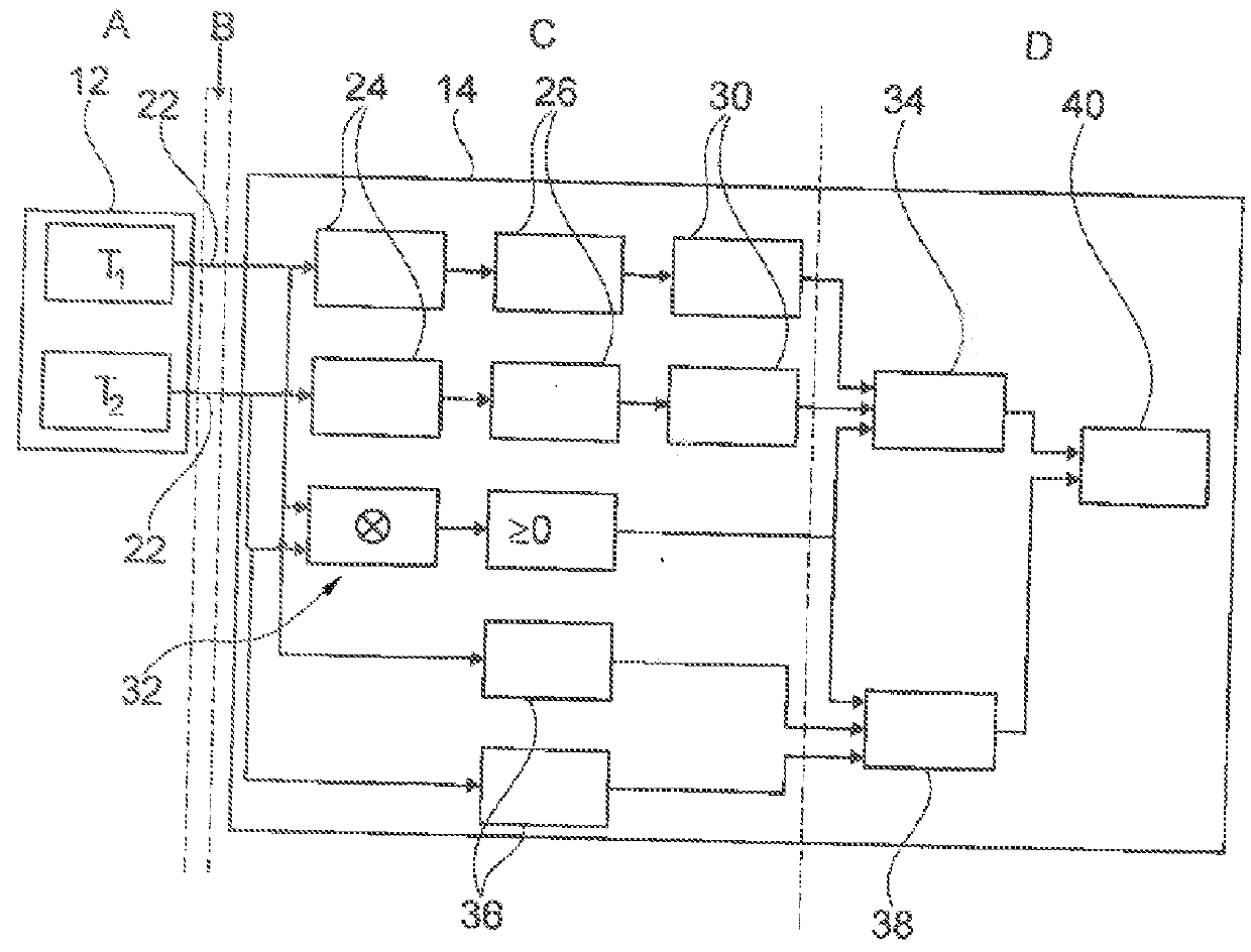
[0035]The sensor 12 comprises a measuring section 18 and a sensor controller 20 which are electrically connected to each other. The measuring section 18 and the sensor controller 20 are located within the sensor 12, which is installed as a finished unit.

[0036]The measuring section 18 is a microsystem, such as a micro-electro-mechanical system (MEMS) or a micro-opto-electro-mechanical system (MOEMS) and is used to capture a particular measur...


PUM


Abstract

A method for detecting a malfunction or defect of a sensor of a vehicle safety device uses a control unit of the vehicle safety device and at least one self-testing sensor which is separate from the control unit and transmits measuring values to the control unit. The following steps are performed:a) The sensor performs the self-test of the sensor, wherein the measuring section of the sensor is activated in a simulated manner in order to generate a test measuring value in response to the simulated activation,b) a signal is transmitted to the control unit which includes at least one of: a ratio of test measuring value to intensity of the simulated activation, a deviation of the test measuring value from the simulated activation and a test measuring value,c) it is checked by means of the control unit whether at least one of the ratio, the deviation and the measuring value is plausible,d) the control unit determines that the sensor has malfunctioned or is defective if at least one on the ratio, the deviation and the test measuring value is considered to be non-plausible.

Description

RELATED APPLICATION[0001]This application claims priority from German Patent Application No. 10 2016 105 016.4, filed Mar. 17, 2016, the subject matter of which is incorporated herein by reference.TECHNICAL FIELD[0002]The invention relates to a method for detecting a malfunction of a sensor of a vehicle safety device.BACKGROUND OF THE INVENTION[0003]In vehicle safety technology, data regarding the current driving situation of the vehicle is collected using sensors. This data is made available to the vehicle safety devices, e.g. airbag systems or vehicle dynamics control, such as ESP or ESC which can control the vehicle or parts thereof using this data.[0004]The measuring section of these sensors is e.g. a microsystem such as a micro-electro-mechanical system (MEMS element) or a micro-opto-electro-mechanical system (MOEMS element).[0005]If one of these sensors malfunctions or supplies false measuring values owing to a defect, the measuring values of this malfunctioning sensor must be...

Claims


Application Information

Patent Timeline
IPC IPC(8): G01P21/00B60W50/02B60R21/0132
CPCB60R21/0132B60R2021/0119G01P21/00B60W50/0205B60W2050/021B60R2021/01327B60R16/02G01D18/00B60R21/0173
Inventor WEILAND, DOMINIKMELTON, PAULMUNCH, CARL A.BUNTZ, OLIVERWEBERT, MATTHIAS
Owner TRW AUTOMOTIVE GMBH
Why Eureka
Try Eureka