
Polymer flow control device

a technology of flow control and polymer, which is applied in fluid dynamics, sealing/packing, and well accessories, etc., can solve the problems of poor macroscopic sweep efficiency, inability to stabilize fronts and viscous fingering, etc., and achieves reduction of axial forces, reduces shear, and reduces polymer degradation.

Active Publication Date: 2019-08-13
TYPHONIX +1
View PDF13 Cites 0 Cited by
  • Summary
  • Abstract
  • Description
  • Claims
  • Application Information

AI Technical Summary

Benefits of technology

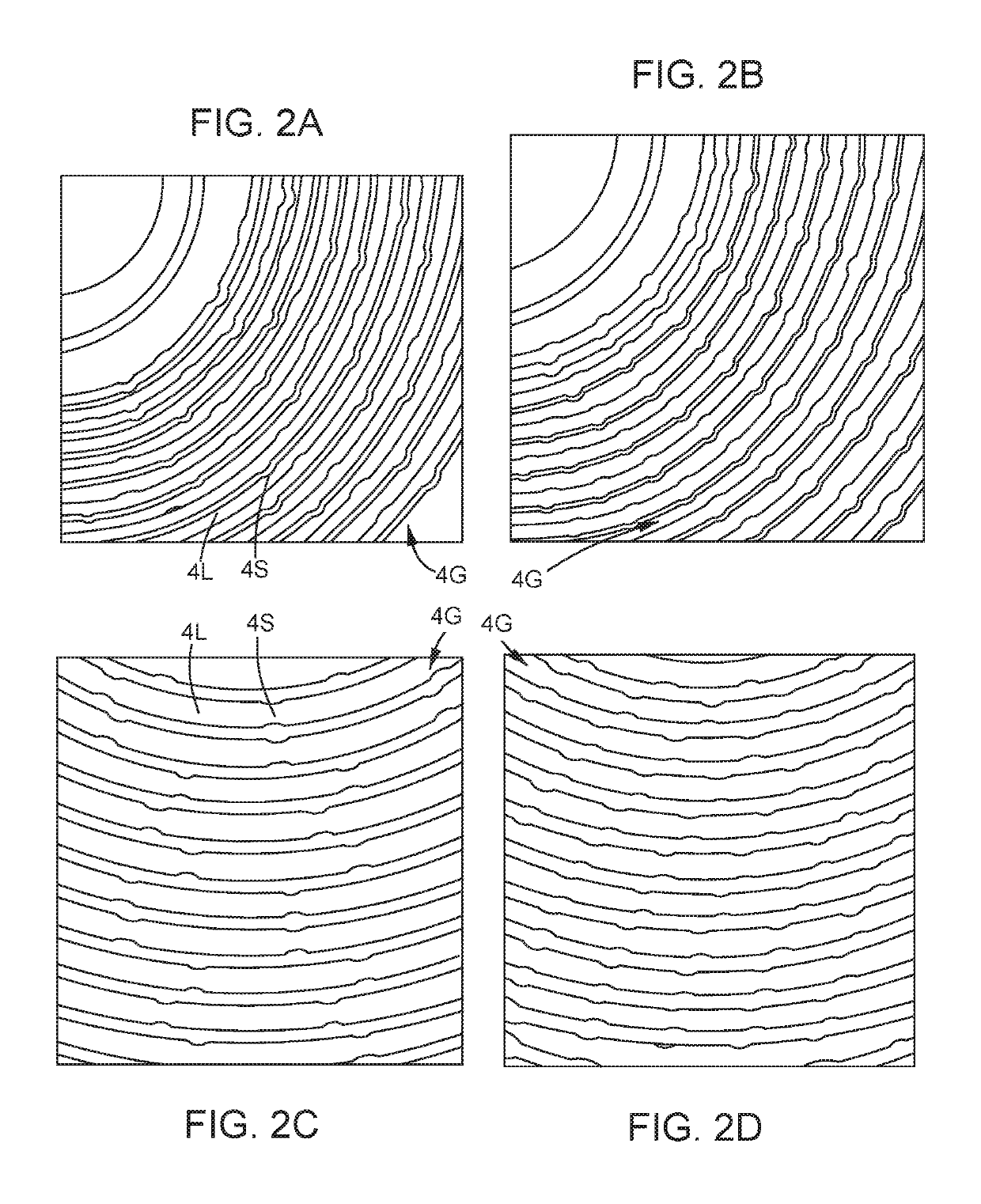
[0018]Without wishing to be bound by theory, the device of the invention provides a prescribed pressure loss (choking) combined with minimal polymer degradation, in a relative compact, low weight unit, by keeping strain, strain rate, fluid acceleration, deceleration and direction changes below limits over which the polymer molecules break up and viscosity decreases. More specifically, water-soluble polymers used for mobility control application are in general high molecular weight polymers that are very sensitive to mechanical degradation. When submitted to extensional flows such as those encountered in contractions or turbulent eddies, polymer coils undergo a coil-stretch transition as stretched. As the chain starts to extend, hydrodynamic force exerted through the friction of the solvent on the stretched chain is increased, and can lead to chain rupture at a critical strain rate {dot over (ε)}R. At a given polymer concentration, viscosity is decreasing when molecular weight of the polymer is decreasing. Consequently, chain break up leads to a decrease of the solution viscosity. This degradation is irreversible along with the viscosity loss. In a classical plug and cage choke valve, part of the pressure drop is coming from the passage through small holes and from the collision of the fluid at the interior of the cage. During its passage through the holes, the fluid is subjected to very high strain rate (the extensional component of this type of flow is very high). At the interior of the cage, the fluid is once again submitted to the elongational component of the highly turbulent flow. It explains why polymer degradation is very high in this kind of valve. The invention aims at minimizing the extensional component of the flow and thus, minimizing polymer degradation. However, compared to a design with a constant cross section, additional pressure drop is created thanks to the elastic behavior of the polymer solution. Indeed, in extensional flow, polymer is developing extensional viscosity which can be very high compared to the shear viscosity. There exists a window of strain rate in which polymer develops elongational viscosity without being degraded. By varying the cross section of the channel, we promote the apparition of the elongational viscosity but keep the strain rate under its critical value to minimize polymer degradation. With serpentine geometry, we promote the development of elastic turbulence.
[0043]Parts of the device of the invention can be made out of polymer or composite material, instead of steel or other metal, if the forces acting on the device and parts thereof permit. For example, the discs or cone-like plates comprising spiral shaped grooves or spiral shaped openings can be made of polymer, for example POM (polyoxymethylene) or PEEK (polyetheretherketone), or composite material. Grooves can be made by machining / milling, molding, such as injection molding, casting or otherwise. Spiral shaped openings can be made by punching, pressing, molding, casting, forging or otherwise. Alternating layers of polymer or composite discs or plates, with spiral shaped grooves or openings, between metal / alloy discs or cone like plates without said grooves or openings, represent preferable embodiments of the invention. On each spiral disc, the pressure difference in channels separated by a wall (in the radial direction) is small (DP=DP valve / number of turns). As a consequence, discs can be machined or made in polymer or composite material. It has the advantage to reduce the weight and the cost of the valve. In addition to polymer injection application, this low cost valve can be used for water injection.

Problems solved by technology

Often however, water mobility is higher than oil mobility leading to unstable fronts and viscous fingering.
As a consequence, the macroscopic sweep efficiency is poor, large areas of the oil-bearing formation are not swept, and oil is left in place.

Method used


Image

  • Polymer flow control device
  • Polymer flow control device
  • Polymer flow control device

Examples


Embodiment Construction

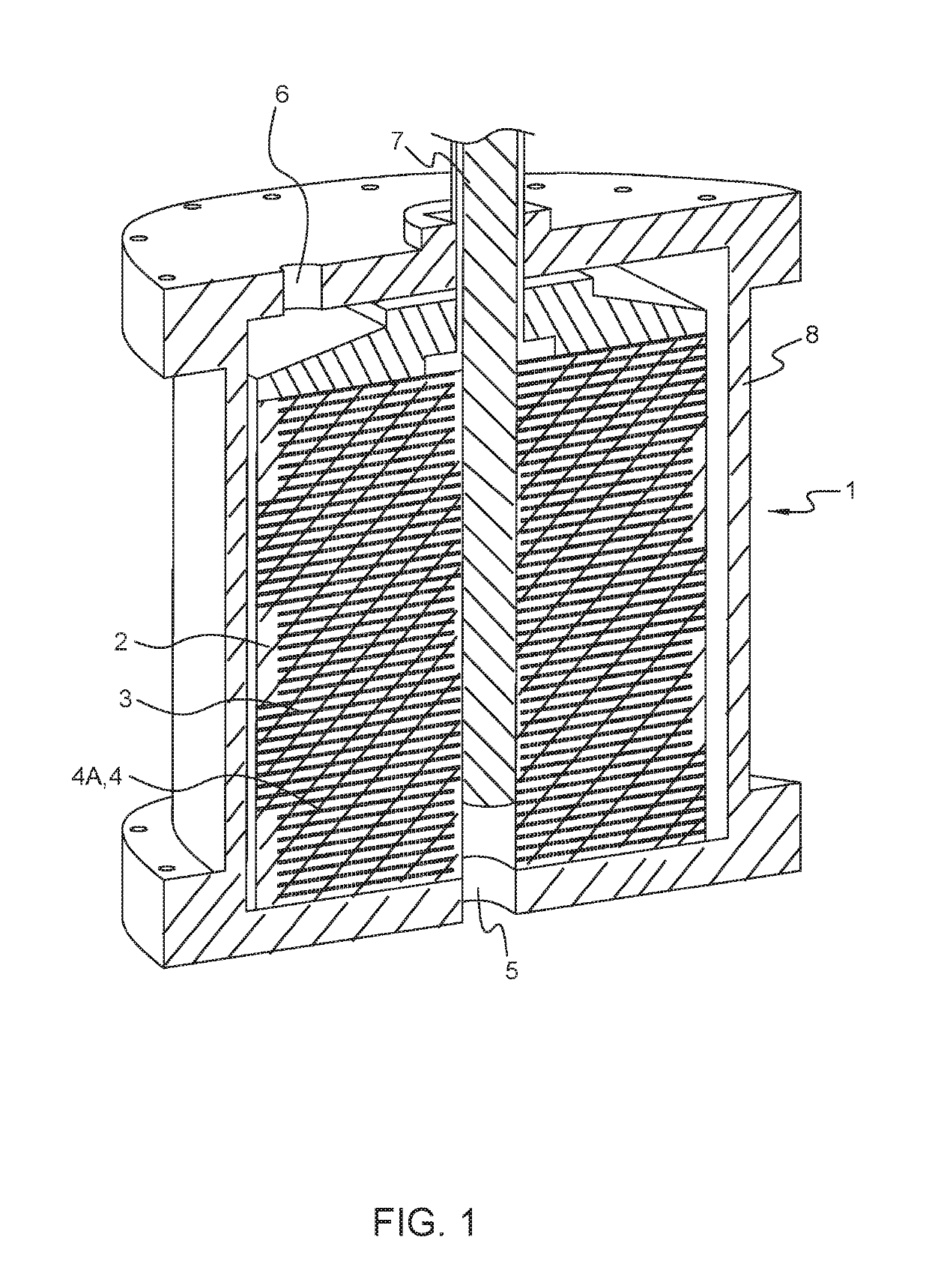
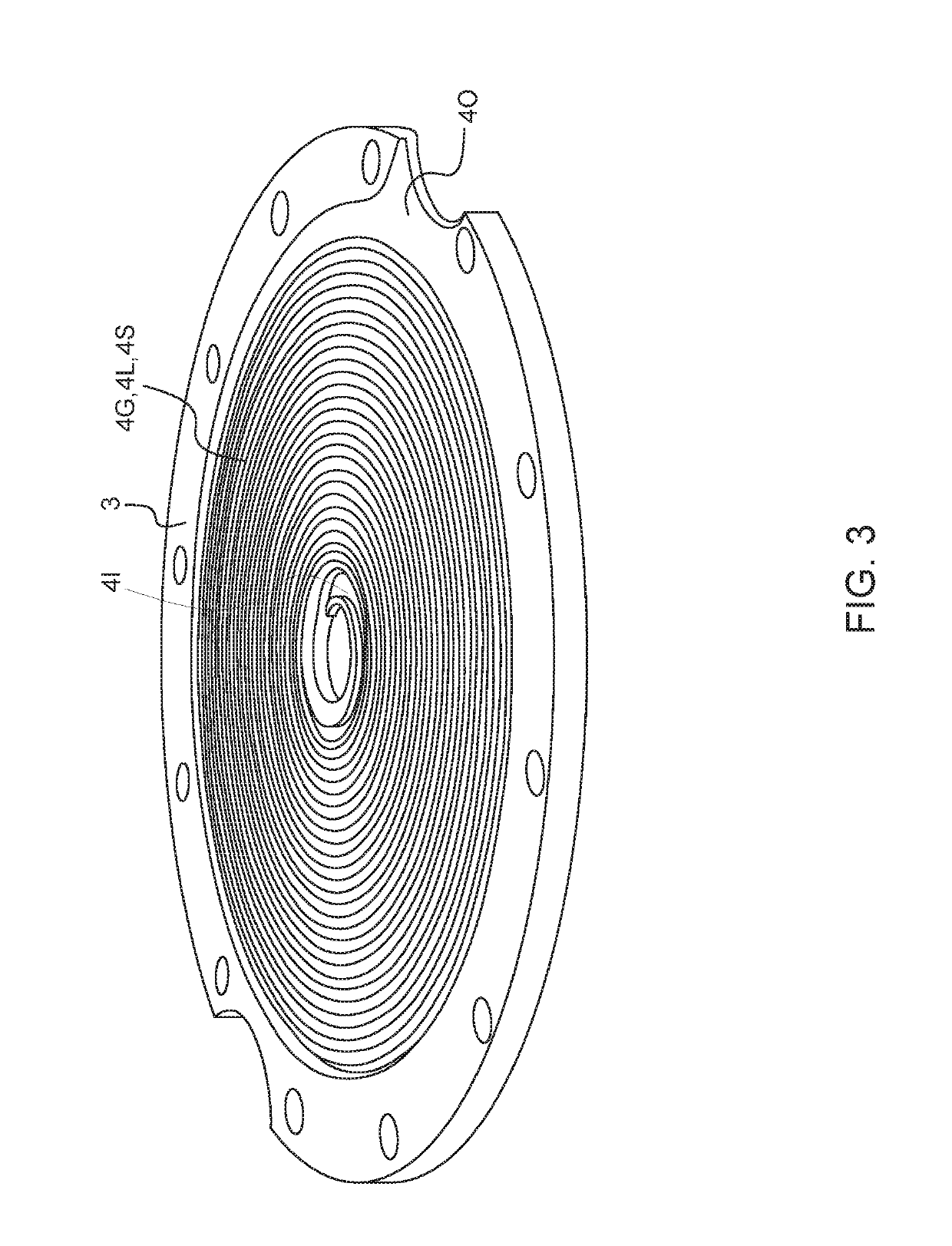
[0066]FIG. 1 illustrates a water injection flow control device 1 of the invention. The device comprises a stack 2 of discs 3, the discs as stacked comprises in substance spiral shaped flow conduits 4, said spiral shaped flow conduits comprises sections in series with alternating large and small cross section area for flow 4A, wherein a ratio of at least one dimension in the flow conduit transverse to a central flow line through said sections of large and small cross section areas for flow is in a range 1.05-10. The device comprises an inlet 5, or part thereof, coupled to an inner end of the spiral shaped flow conduits, an annular outlet 6 operatively coupled to an outer end of said conduits, and a control member 7 arranged in the inlet. In addition, the device comprises a housing 8, containing the stack of discs.

[0067]The illustrated embodiment of the device of the invention comprises a stack of discs with a spiral shaped groove on one side of each disc, the other side is flat or pl...


PUM


Abstract

A water injection flow control device includes a stack of discs or cone-like plates that form spiral-shaped flow conduits. The spiral-shaped flow conduits form at least one revolution about a central point or axis and depart or approach the central point or axis for each revolution. At least some of the spiral-shaped flow conduits have sections in series with alternating cross sectional area for flow and at least some have sections with a serpentine-type shape for flow along the spiral-shaped flow conduits. The spiral-shaped flow conduits have an inlet coupled to an inner or outer end of the spiral shaped flow conduits, an outlet coupled to the other end of the spiral-shaped conduits, and a control member.

Description

FIELD OF THE INVENTION[0001]The present invention relates to injection of water containing viscosity-enhancing polymers into reservoirs, for enhanced oil recovery.BACKGROUND OF THE INVENTION AND PRIOR ART[0002]During oil recovery operations, several wells are drilled in a reservoir. They are divided into injection wells and production wells. In most cases, water is forced into the reservoir through the injection wells to maintain the pressure difference with the surface and ensure the flow of oil through the formation; oil is pushed and replaced by the injected water. Often however, water mobility is higher than oil mobility leading to unstable fronts and viscous fingering. As a consequence, the macroscopic sweep efficiency is poor, large areas of the oil-bearing formation are not swept, and oil is left in place. Increasing the viscosity of the injected water enables to decrease the mobility ratio between water and oil and to improve macroscopic sweep efficiency. As a general rule, ...

Claims


Application Information

Patent Timeline
Patent Type & Authority Patents(United States)
IPC IPC(8): E21B34/02F16K47/08E21B43/20F16K47/04F16K47/06F16K47/12F15D1/02
CPCE21B43/20E21B34/02F16K47/04F16K47/08F16K47/12F16K47/06F15D1/02F16K3/32E21B34/025E21B43/12E21B43/16
Inventor JOUENNE, STÉPHANEHUSVEG, TRYGVE
Owner TYPHONIX
Learn More