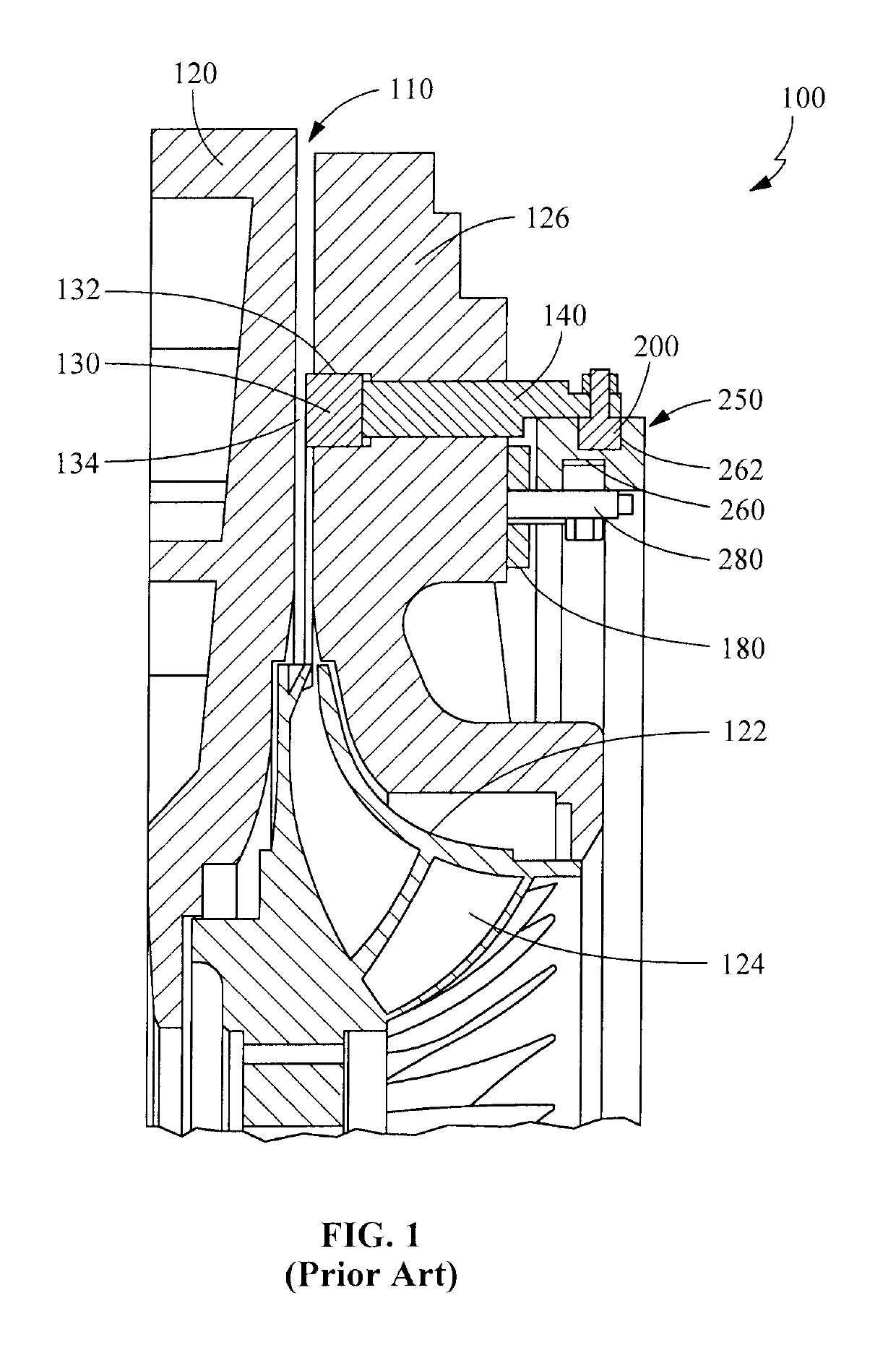
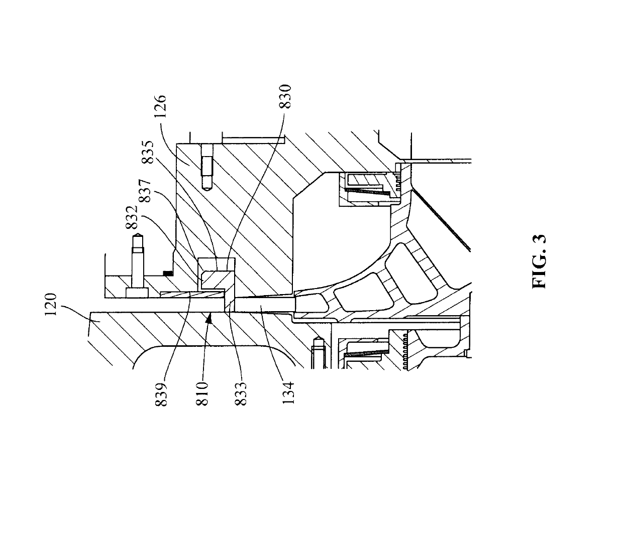
[0009]The present invention provides a variable geometry diffuser (VGD) mechanism. The VGD mechanism includes a diffuser ring extending into a diffuser gap that mitigates stall, as expected of a VGD mechanism. However, the VGD mechanism of the present invention extends further into the diffuser gap than prior art VGD mechanisms so that the VGD mechanism of the present invention may be used to control other operational functions. Thus the VGD mechanism may be used to minimize compressor backspin and associated transient loads during compressor shut down by preventing a reverse flow of refrigerant gas through the diffuser gap during compressor shutdown. The reverse flow of refrigerant gas is prevented because the diffuser gap is substantially blocked by the full extension of the diffuser ring. The VGD mechanism further provides for better and more efficient compressor turn-down, reducing the need for significant hot gas bypass during low cooling capacity operation. During start-up, transient surge and stall also can be effectively eliminated as the variable geometry diffuser ring can be positioned to impede gas flow through the diffuser gap as load and impeller speed increase, thereby alleviating the problems caused by startup loads at low speeds. The VGD mechanism of the present invention can be used for capacity control as well, so as to achieve more effective turndown at low loads.
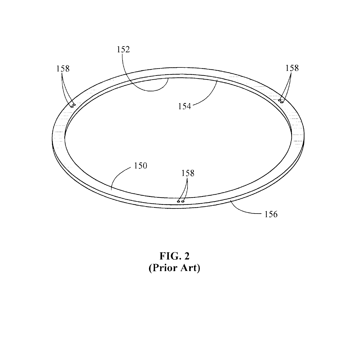
[0010]While the diffuser ring extends across the diffuser gap to accommodate reduced gas flow through the diffuser gap during normal operation under certain conditions, the diffuser ring must extend substantially completely across the diffuser gap during shut-down and start-up since the gas flow is significantly reduced as the impeller ramps up to speed during start-up or decreases its speed during shut-down. The outer edge of the diffuser ring comprises a flange that, when fully extended across the diffuser gap, substantially impedes gas flow through the diffuser gap. The axial force on the diffuser ring is a function of the pressure differential on either side of the ring and the area of the ring. When the diffuser ring is extended into the diffuser gap, high velocity gas passes over the outer face of the ring creating a low pressure area. Higher pressure gas on a first side of the ring provides a force on the first side of the ring. The overall axial force on the ring is the difference in gas pressure between the first side of the ring and the second, opposite side of the ring multiplied by the radial face area of the ring. The axial force on the ring may be minimized by reducing the area of the ring. By reducing the radial width of the ring extending into the diffuser gap, the axial force on the ring is reduced proportionally to the width of the ring. While the width (thickness) of the ring may be reduced to lower the load, the ring must be sufficiently thick to accommodate the increased radial forces from flow past the ring or it will not act to block gas flow effectively and may be subject to operational failures. The thickness of the ring will vary among compressors depending upon the capacity of the compressor, the thickness of the ring being relative, that relation depending on several factors, the most important being the net radial flow forces acting on the first, inner cylindrical surface and second, outer cylindrical surface of the diffuser ring, particularly as the impeller slows from operational speed during shut-down or ramp-up to operational speed during start-up. Larger compressors with larger impellers will generate higher flow forces and experience higher loads, requiring thicker rings. But, regardless of compressor size, reducing the axial forces on the ring reduces the forces necessary to operate the VGD mechanism.
[0012]Not only must the ring be sufficiently thick to handle the radial loads over the life of the compressor, the ring must also interface with the opposed housing to provide a gap that is uniform around its circumference and must effectively mate with an interior face of the housing that also must be dimensioned to be uniform. If the gap is not substantially uniform, that is, outside of allowable tolerances, pressurized gas will leak through the gap at locations where the gap is larger than allowable, defeating the purpose of the closed diffuser ring without reducing the problems related to capacity control, surge, that occurs during shutdown and start-up, and other operational improvements associated with the improved VGD mechanism. Whereas elimination of such leakage around the diffuser ring during shut down and start-up was not an imperative with prior art designs, to be effective, both the diffuser ring and the opposed interior face of the housing of the present invention must have carefully controlled mating surfaces so that proper operation of the VGD mechanism can be accomplished over a range of conditions.
[0013]Thus, in the present invention, in order to affect control of gas flow through the diffuser gap, physical changes extending the travel of the diffuser ring into the diffuser gap are required for the VGD mechanism. In addition to extending the length of the diffuser ring into the diffuser gap to allow substantially full closure of diffuser gap, the radial area of the diffuser ring is reduced to reduce the axial forces on the ring in response to the pressure forces. Also, by inclusion of sensors, a controller can now monitor the position of the diffuser ring accurately and direct the actuator mechanism to accurately move the diffuser ring between positions that are fully open and fully closed in response to compressor operating conditions. Faster-acting mechanisms can be used to achieve better control of the ring position and respond to chiller system transients such as startup with pressure differential across the compressor or power failure shutdowns.
[0014]An additional benefit of the improved variable geometry diffuser of this invention is the elimination of the need for pre-rotation vanes for capacity control and startup management. Pre-rotation vanes and their mechanisms are complex, expensive, and require their own drive mechanisms and controls.


