
Brake rotor with decorative insert

a technology of brake rotor and insert, which is applied in the direction of brake discs, brake drums, transportation and packaging, etc., can solve the problems of many manufactured components such as brake rotors, unmarked, and difficult to maintain effective marking, and can quickly wear in response to everyday driving conditions

Active Publication Date: 2019-08-13
GM GLOBAL TECH OPERATIONS LLC
View PDF10 Cites 2 Cited by
  • Summary
  • Abstract
  • Description
  • Claims
  • Application Information

AI Technical Summary

Benefits of technology

The patent text discusses the challenges of marking components of a disk brake system, such as brake rotors. These components are often unmarked or have markings that quickly wear down during use. The technical effect of this patent is to provide a solution for effectively marking these components to improve their durability and performance.

Problems solved by technology

Many manufactured components, such as brake rotors, are unmarked due to difficulties of marking.
For components that will experience wear during use, effective marking is challenging or impossible to maintain.
Regarding brake rotors, for example, a marking including print, a label, or etching on a frictional surface can quickly wear in response to everyday driving conditions.

Method used


Image

  • Brake rotor with decorative insert
  • Brake rotor with decorative insert
  • Brake rotor with decorative insert

Examples


Embodiment Construction

[0033]The following description is merely exemplary in nature and is not intended to limit the present disclosure, its application or uses. It will be understood that, although the terms first, second, third etc. may be used herein to describe various elements, components, and / or sections, these elements, components, and / or sections should not be limited by these terms. These terms are only used to distinguish one element, component, or section from another element, component, or section. Thus, a first element, component, or section discussed below could be termed a second element, component, or section without departing from the teachings of the present disclosure.

[0034]Unless otherwise defined, all terms (including technical and scientific terms) used herein have the same meaning as commonly understood by one of ordinary skill in the art to which this disclosure belongs. It will be further understood that terms, such as those defined in commonly used dictionaries, should be interp...


PUM


Abstract

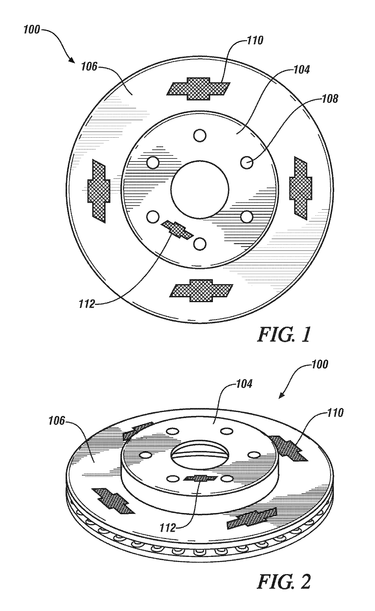
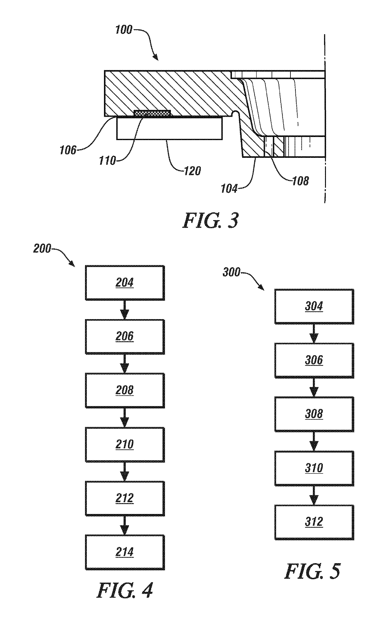
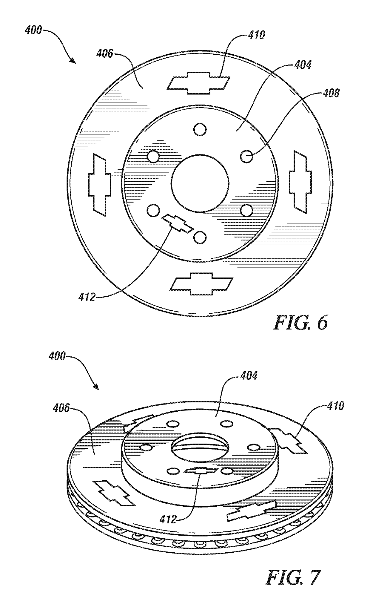
A brake rotor comprising a brake pad wear surface; a hat surface; and a decorative insert comprising an insert material, the decorative insert disposed on the brake pad wear surface, the hat surface, or both; wherein at least one of a friction coefficient between the decorative insert and a brake pad is substantially the same as a friction coefficient between the brake pad wear surface and the brake pad, a wear rate of the decorative insert is substantially the same as or greater than a wear rate of the brake pad wear surface, or a wear rate of the decorative insert is substantially the same as or greater than a wear rate of the hat surface; and at least a portion of the decorative insert is visible on the brake pad wear surface, the hat surface, or both.

Description

INTRODUCTION[0001]The subject disclosure relates to a brake rotor having a decorative insert.[0002]Disk brakes are commonly used for slowing or stopping the rotation of a wheel of a vehicle. Generally, a disk brake system includes a brake rotor connected to the wheel and / or an axle of the vehicle and a caliper. Many manufactured components, such as brake rotors, are unmarked due to difficulties of marking. For components that will experience wear during use, effective marking is challenging or impossible to maintain. Regarding brake rotors, for example, a marking including print, a label, or etching on a frictional surface can quickly wear in response to everyday driving conditions.[0003]Accordingly, it is desirable to provide a method to effectively and lastingly mark components without adding prohibitive cost to the manufacturing process or compromising component quality.SUMMARY[0004]In one exemplary embodiment, a brake rotor comprises a brake pad wear surface, a hat surface, and ...

Claims


Application Information

Patent Timeline
Patent Type & Authority Patents(United States)
IPC IPC(8): F16D65/12B60R13/00F16D65/02
CPCF16D65/127B60R13/005F16D65/122F16D65/125F16D2250/0038F16D2200/0004F16D2200/0039F16D2250/0015F16D2065/1328F16D65/12F16D2065/13
Inventor METTRICK, CHRISTOPHER J.RIEFE, MARK T.HOLLY, MICHAEL L.WEBSTER, JAMES A.WALKER, MICHAEL J.SACHDEV, ANIL K.
Owner GM GLOBAL TECH OPERATIONS LLC
Learn More