Energy absorbing flange for meltable fuze plug
- Summary
- Abstract
- Description
- Claims
- Application Information
AI Technical Summary
Benefits of technology
Problems solved by technology
Method used
Image
Examples
Embodiment Construction
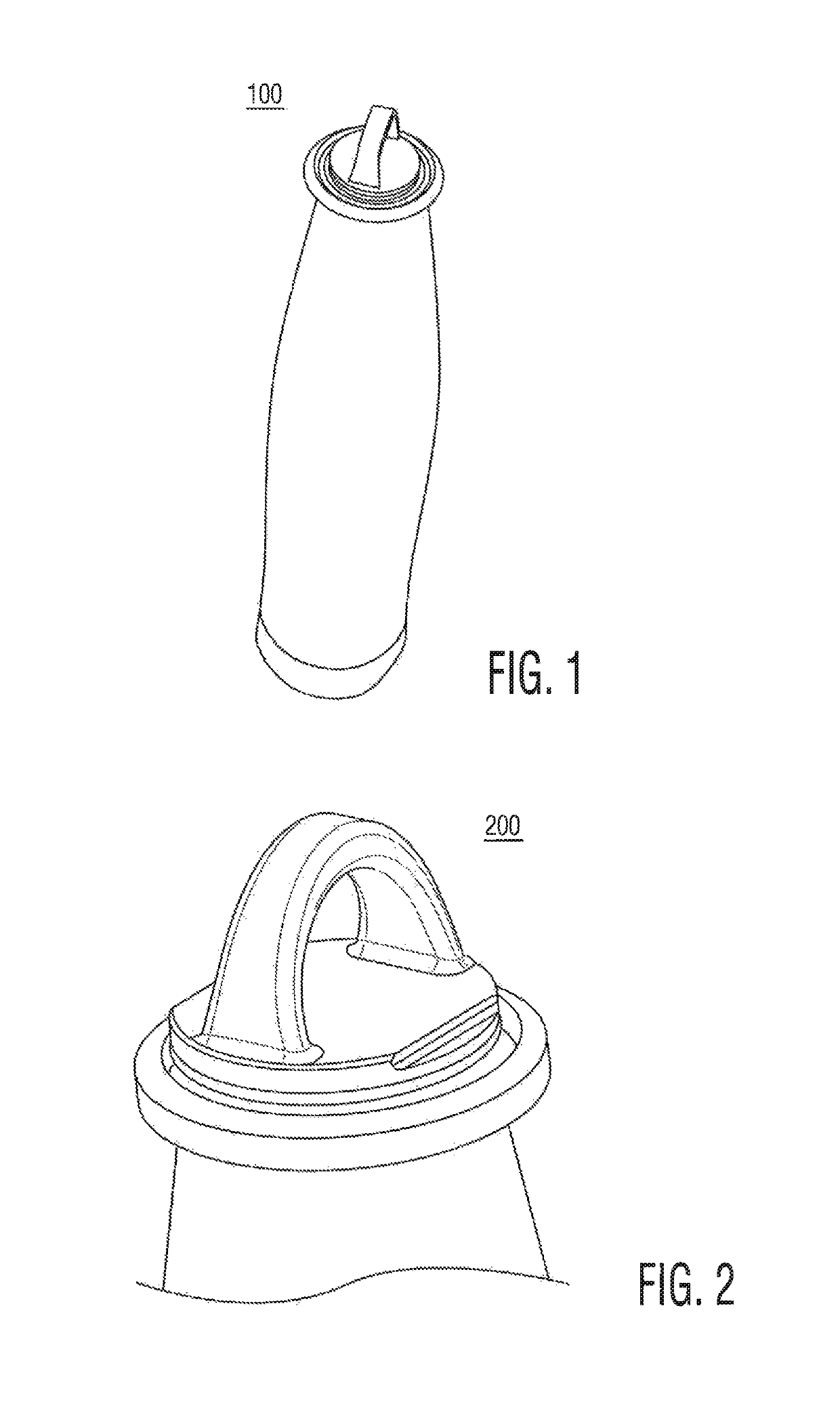
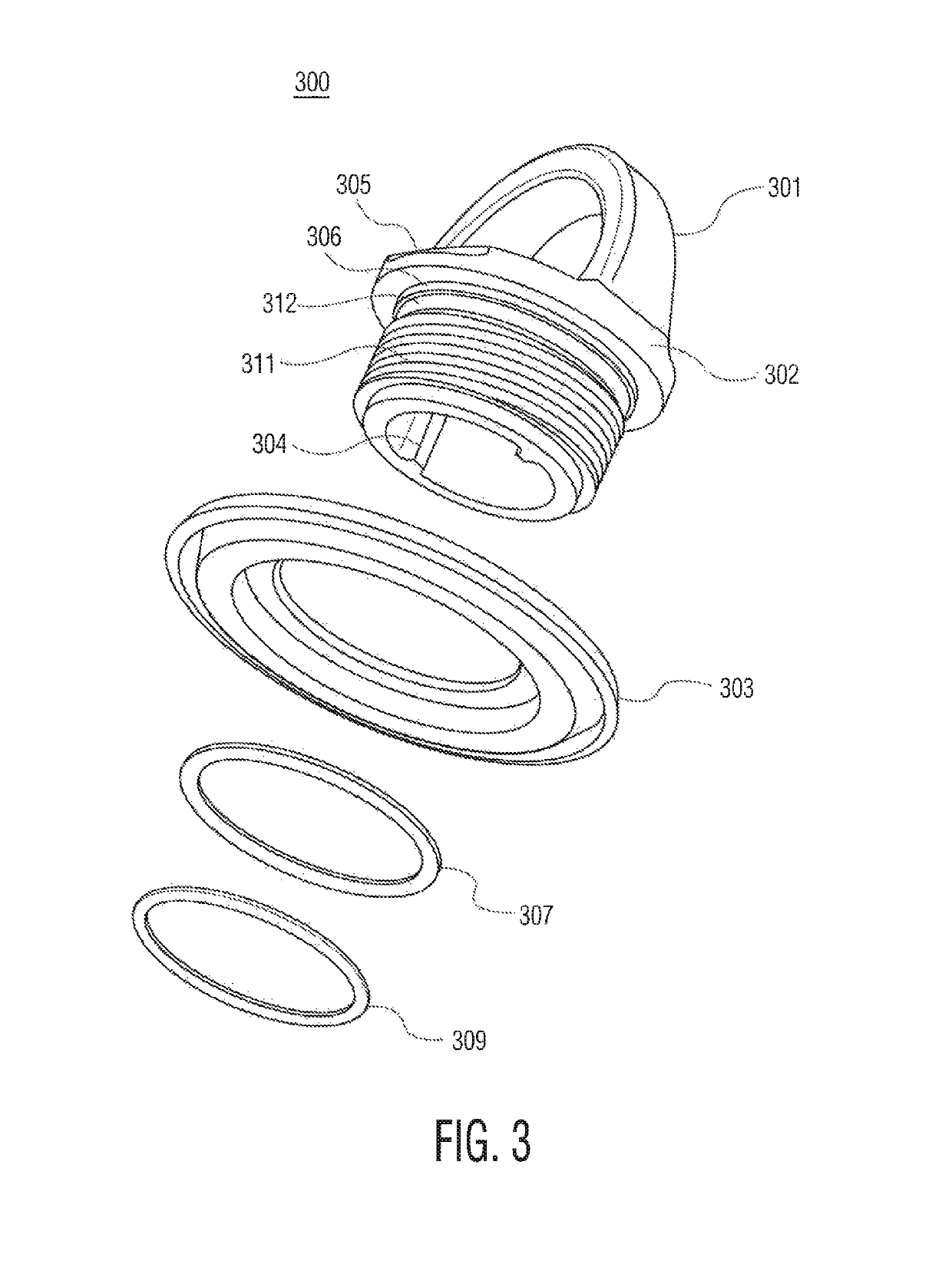
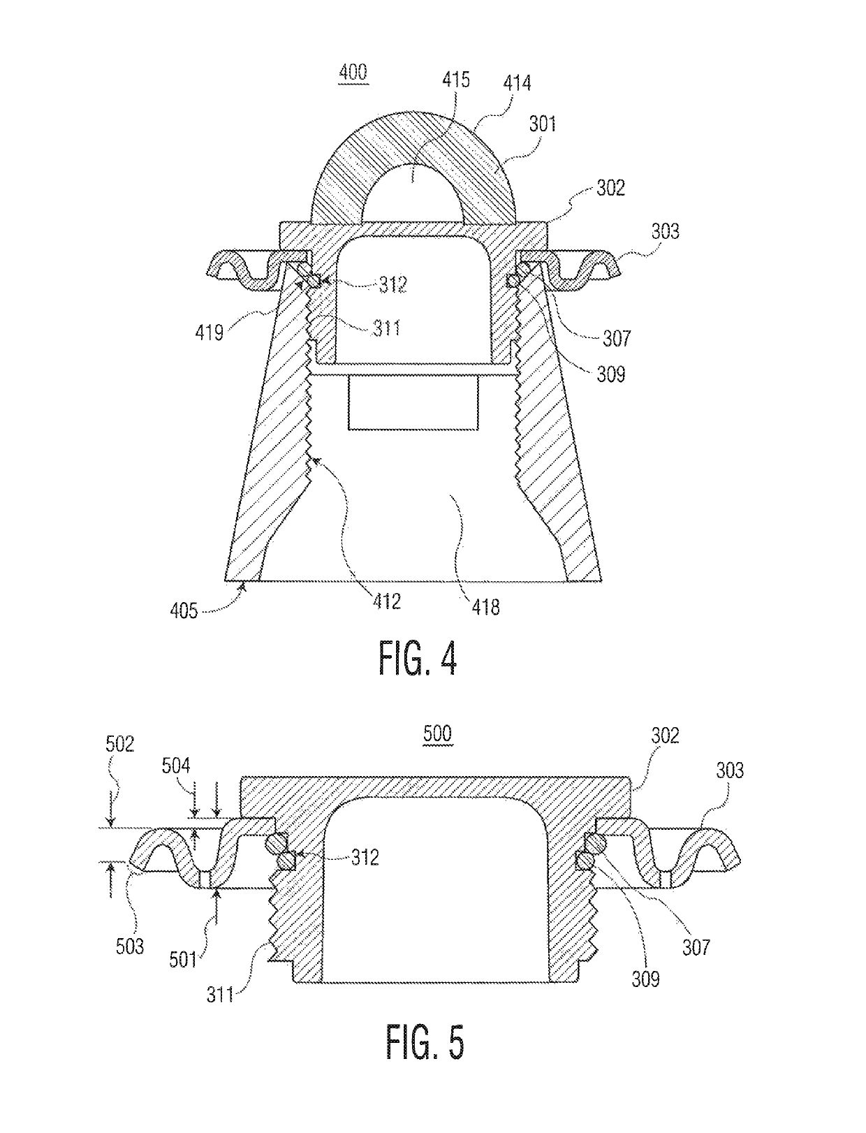
[0021]FIG. 1 shows a top isometric view of a munition 100 having a meltable fuze plug according to this invention. FIG. 2 is a more close up view of this meltable fuze plug in place in a munition 200. FIG. 3 is an exploded view of a meltable fuze plug 301 according to this invention, in place atop an ogive 405 (see FIG. 4) of a munition having a hollow ogive cavity 418. It has a crescent shaped meltable fuze handle 414 with a lunette 415. It is shown with its upper flange 302, internal cavity ribs 304, notches 305 on the flange to aid in turning; a corrugated washer 303, a circumferential smooth surface 306, large O-ring 307, slightly below the circumferential smooth surface, a circumferential groove 312, and a small O-ring 309 sitting in the groove. Upper flange 302 should be of diameter sufficient to eliminate any interference from a maximal 2.5625 inch diameter hole size for fuze plug openings on many wood pallet top covers for the rounds, to insure ejection of, at least, the pla...
PUM
 Abstract
Description
Claims
Application Information
 - R&D
- Intellectual Property
- Life Sciences
- Materials
- Tech Scout
- Unparalleled Data Quality
- Higher Quality Content
- 60% Fewer Hallucinations
Browse by: Latest US Patents, China's latest patents, Technical Efficacy Thesaurus, Application Domain, Technology Topic, Popular Technical Reports.
© 2025 PatSnap. All rights reserved.Legal|Privacy policy|Modern Slavery Act Transparency Statement|Sitemap|About US| Contact US: help@patsnap.com


