
Strain amount calculation system, strain amount calculation method, and storage medium

a calculation system and strain amount technology, applied in the field of strain amount calculation system, strain amount calculation method, storage medium, can solve problems such as difficult comparison

Active Publication Date: 2019-08-13
TOYOTA PRODN ENG CORP
View PDF21 Cites 2 Cited by
  • Summary
  • Abstract
  • Description
  • Claims
  • Application Information

AI Technical Summary

Problems solved by technology

Thus, the comparison can be difficult.

Method used


Image

  • Strain amount calculation system, strain amount calculation method, and storage medium
  • Strain amount calculation system, strain amount calculation method, and storage medium
  • Strain amount calculation system, strain amount calculation method, and storage medium

Examples


embodiment

[0024]Configuration

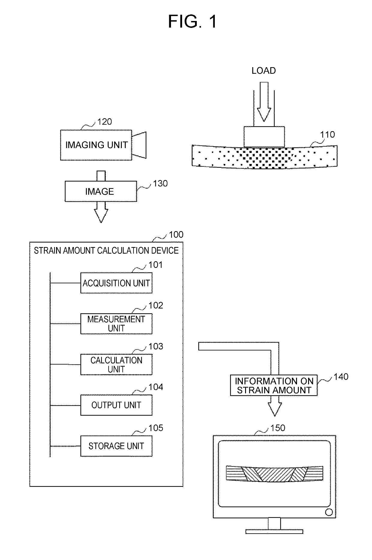
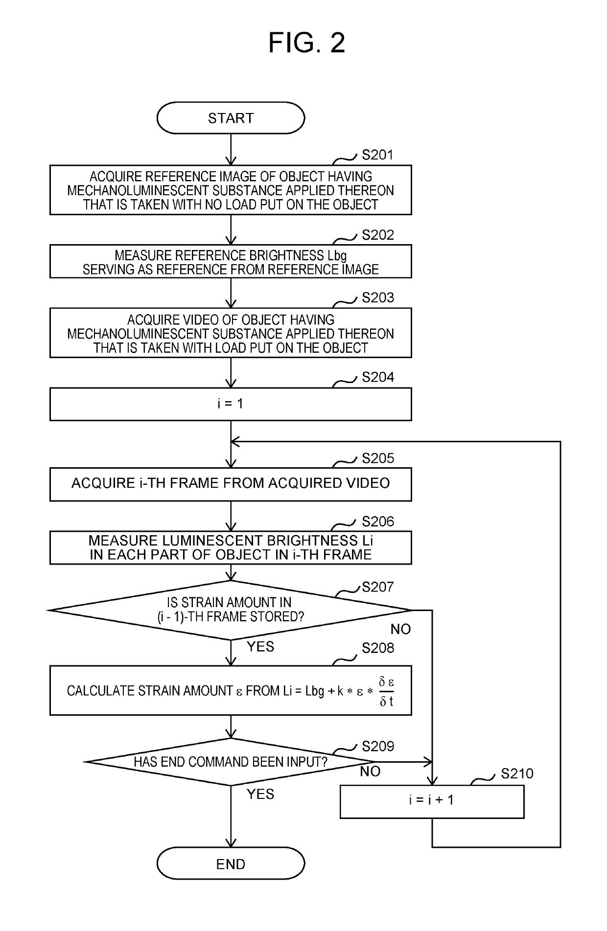
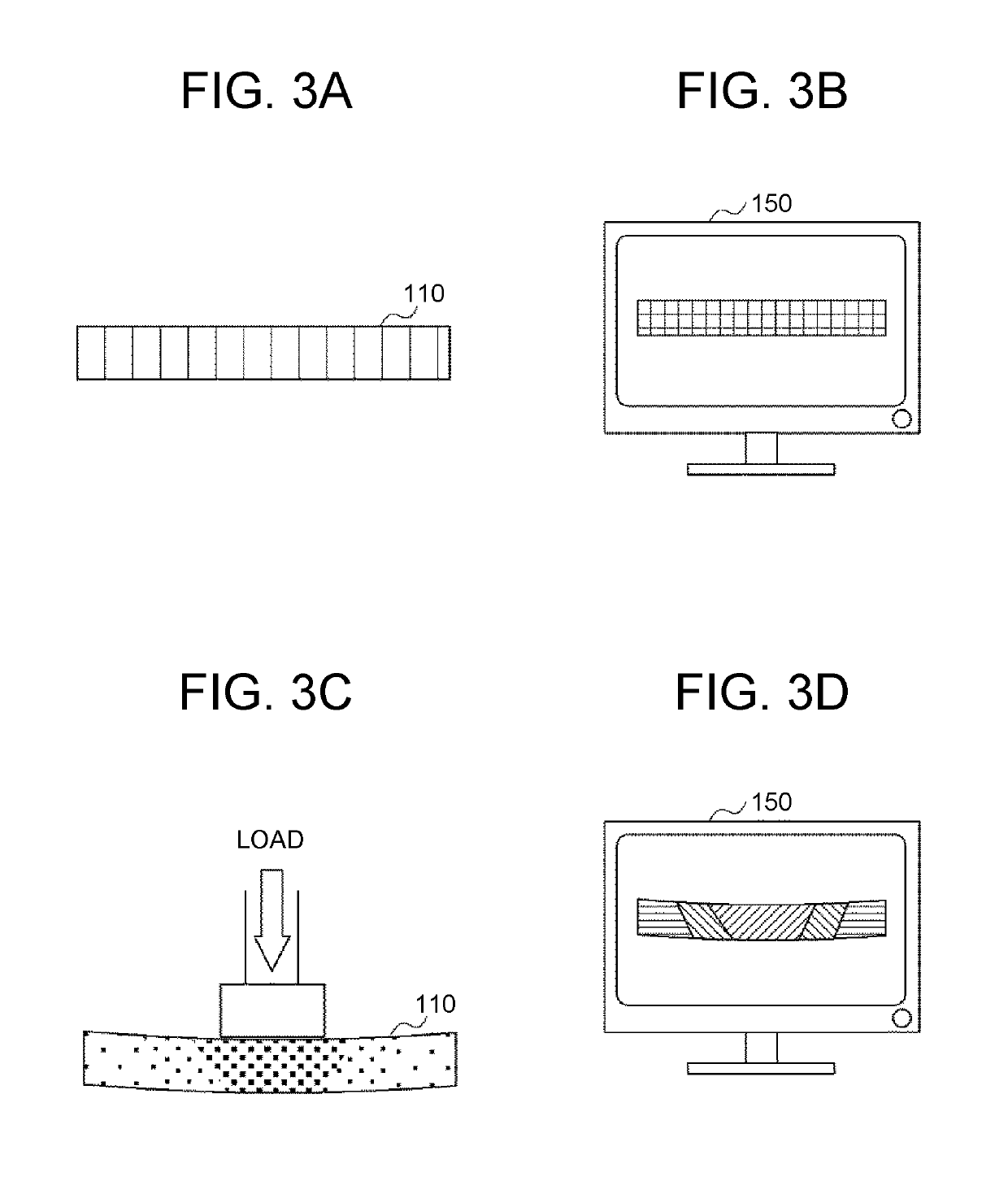
[0025]FIG. 1 is a view showing the configuration of a strain amount calculation system including a strain amount calculation device 100. In the strain amount calculation system, an imaging unit 120 takes images of an object 110 having a mechanoluminescent substance applied thereon, and the strain amount calculation device 100 calculates an amount of strain (stress) on the object 110 based on luminescent brightness from an image 130 obtained by imaging. Then, a display device 150 displays an image of the object 110 rendered as a color contour map based on the strain amount calculated by the strain amount calculation device 100. The strain amount calculation device 100 in the system will be described in detail below.

[0026]As shown in FIG. 1, the strain amount calculation device 100 includes an acquisition unit 101, a measurement unit 102, a calculation unit 103, an output unit 104, and a storage unit 105.

[0027]The acquisition unit 101 is a communication interface ha...


PUM

PropertyMeasurementUnit
luminescent brightnessaaaaaaaaaa
color contour mapaaaaaaaaaa
resistance to stressaaaaaaaaaa

Abstract

A strain amount calculation system includes an imaging unit, and a strain amount calculation device that acquires an image taken by the imaging unit, measures luminescent brightness from the acquired image, calculates an amount of strain on the object caused by a load on the object, based on a temporal change in the measured luminescent brightness, and outputs information on the calculated strain amount.

Description

INCORPORATION BY REFERENCE[0001]The disclosure of Japanese Patent Application No. 2017-010466 filed on Jan. 24, 2017 including the specification, drawings and abstract is incorporated herein by reference in its entirety.BACKGROUND1. Technical Field[0002]The present invention relates to a strain amount calculation system that calculates an amount of strain on an object, a strain amount calculation method, and a storage medium.2. Description of Related Art[0003]In recent years, computer-aided engineering (CAE) has been often used in designing various products and parts. CAE-based design processes include inspection on resistance to stress etc.[0004]One possible technique for measuring a stress on an object is to use a stress measurement system that calculates a stress on an object to be measured (e.g., see Japanese Patent Application Publication No. 2006-284393 (JP 2006-284393 A)). The stress measurement system described in JP 2006-284393 A detects the luminescent intensity of a mecha...

Claims


Application Information

Patent Timeline
Patent Type & Authority Patents(United States)
IPC IPC(8): G01L1/00G01L1/24G06T11/20G06T7/00G01N19/00G01N3/08G01N21/70G01N21/88
CPCG01L1/24G01N3/08G01N19/00G06T11/20G06T7/97G01N21/8803G01N21/70G01N3/068G01N2203/0647G01N2203/0652G01L1/241
Inventor SAKAMOTO, TAKUYAISHIDA, YUKI
Owner TOYOTA PRODN ENG CORP
Learn More