
Tunnel illumination intelligent control system and control method

An intelligent control system and tunnel lighting technology, applied in the field of lighting, can solve the problems of complicated wiring circuits, inability to adjust, power line pulse interference, etc., to prevent traffic accidents in tunnels, reduce power waste, and facilitate control and operation.

Inactive Publication Date: 2015-09-16
SHANDONG BAISHIDA LIGHT IND TECH
View PDF6 Cites 9 Cited by
  • Summary
  • Abstract
  • Description
  • Claims
  • Application Information

AI Technical Summary

Problems solved by technology

However, this hierarchical control mode is too simple, and cannot be adjusted in time according to the actual conditions of the tunnel environment, resulting in waste of electric energy, or unsatisfactory lighting effects leading to traffic accidents
In addition, due to the particularity of tunnel lighting, drivers will have black hole and white hole effects at the entrance and exit of the tunnel. In order to eliminate the driver's "dark adaptation" and "light adaptation" and other visual problems, it is necessary to strengthen the lighting at the entrance and exit sections. It is a waste of electricity and the lighting effect is not good
[0003] On the other hand, PLC signal transmission has many disadvantages, such as: the distribution transformer has a blocking effect on the circuit carrier signal, so that the power carrier signal can only be transmitted within a distribution transformer area; there is a large signal loss between the three-phase power lines; Power lines have their own inherent pulse interference; power lines cause high clipping of the carrier signal
In addition, the wiring loop is complex and cumbersome, causing serious waste and inconvenient use

Method used


Image

  • Tunnel illumination intelligent control system and control method
  • Tunnel illumination intelligent control system and control method
  • Tunnel illumination intelligent control system and control method

Examples


Embodiment Construction

[0035] The present invention will be described in detail below with reference to the accompanying drawings and specific embodiments. The following embodiments are explanations of the present invention, but the present invention is not limited to the following embodiments.

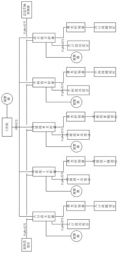
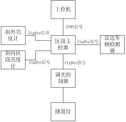
[0036] Such as figure 1 and figure 2 As shown, the intelligent control system for tunnel lighting provided by the present invention includes a luminance meter outside the tunnel, a section luminance meter inside the tunnel, a radar vehicle detector, a tunnel light, a dimming controller, a section master controller and a host computer.

[0037] The brightness meter outside the cave is used to detect the brightness outside the cave.

[0038] The luminance meter in the cave section is used to detect the brightness of each section in the cave; the luminance meter in the cave section includes an entrance section luminance meter and a transition section luminance meter for respectively detecting the brightness ...


PUM


Abstract

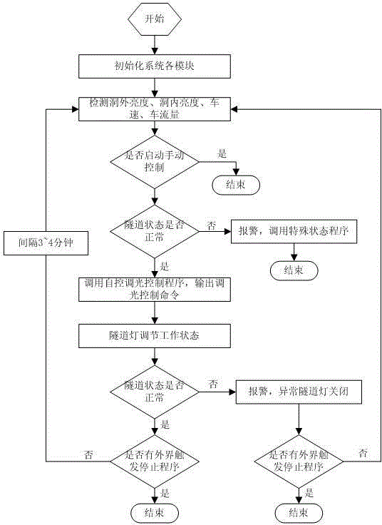
The invention discloses a tunnel illumination intelligence control system and a control method. The tunnel illumination intelligent control system comprises an outside-tunnel luminance meter, an inside-tunnel segment luminance meter, a radar vehicle detector, a tunnel lamp, a light adjustment controller, a segment main controller and an upper computer. The outside-tunnel luminance meter, the inside-tunnel segment luminance meter, and the radar vehicle detector are in wireless communication with the segment main controller through a ZigBee module and transmits an outside-tunnel brightness value, an inside-tunnel brightness value, a vehicle speed and a traffic flow to the segment main controller; the segment main controller is in wireless communication with the light adjustment controller through the ZigBee module and is in wireless communication with the upper computer through a GPRS module; and the segment main controller controls the light adjustment controller to adjust the working state of the tunnel lamp according to a light adjustment control order transmitted by the upper computer. The invention realizes stepless light adjustment without unnecessary electric energy waste, creates good tunnel vision environment, and reduces the wiring waste. The transmission signals are not affected by the continuity of the circuit, which is easy to control and operate.

Description

technical field [0001] The invention relates to the lighting field, and relates to an intelligent control system and a control method for tunnel lighting. Background technique [0002] The tunnel lighting is divided into four sections: the entrance section, the transition section, the middle section and the exit section. There are two transition sections, which are set before and after the middle section. The conventional tunnel lighting control system is controlled by the PLC system, which is usually carried out according to the maximum traffic volume designed. This control method generally has 4 levels of control modes (cloudy, sunny, heavy cloudy, cloudy) , the basic lighting section has day and night 2-level control. Some are combined with light-sensing control, that is, the lights will automatically turn on and off when the set illuminance value is reached. However, this hierarchical control mode is too simple and cannot be adjusted in time according to the actual con...

Claims


Application Information

Patent Timeline
IPC IPC(8): H05B37/02
CPCY02B20/40
Inventor 耿雷李英勇李永薛志超孔令峰
Owner SHANDONG BAISHIDA LIGHT IND TECH
Learn More