Projection display apparatus and projection display system
a technology of projection display and projection display, which is applied in the direction of projection device, color television details, television system, etc., can solve the problems of system configuration becoming complicated, standard cannot catch up with the performance of the display unit, and insufficient dynamic range standard, so as to improve the quality of the hdr image and simple configuration
- Summary
- Abstract
- Description
- Claims
- Application Information
AI Technical Summary
Benefits of technology
Problems solved by technology
Method used
Image
Examples
first embodiment
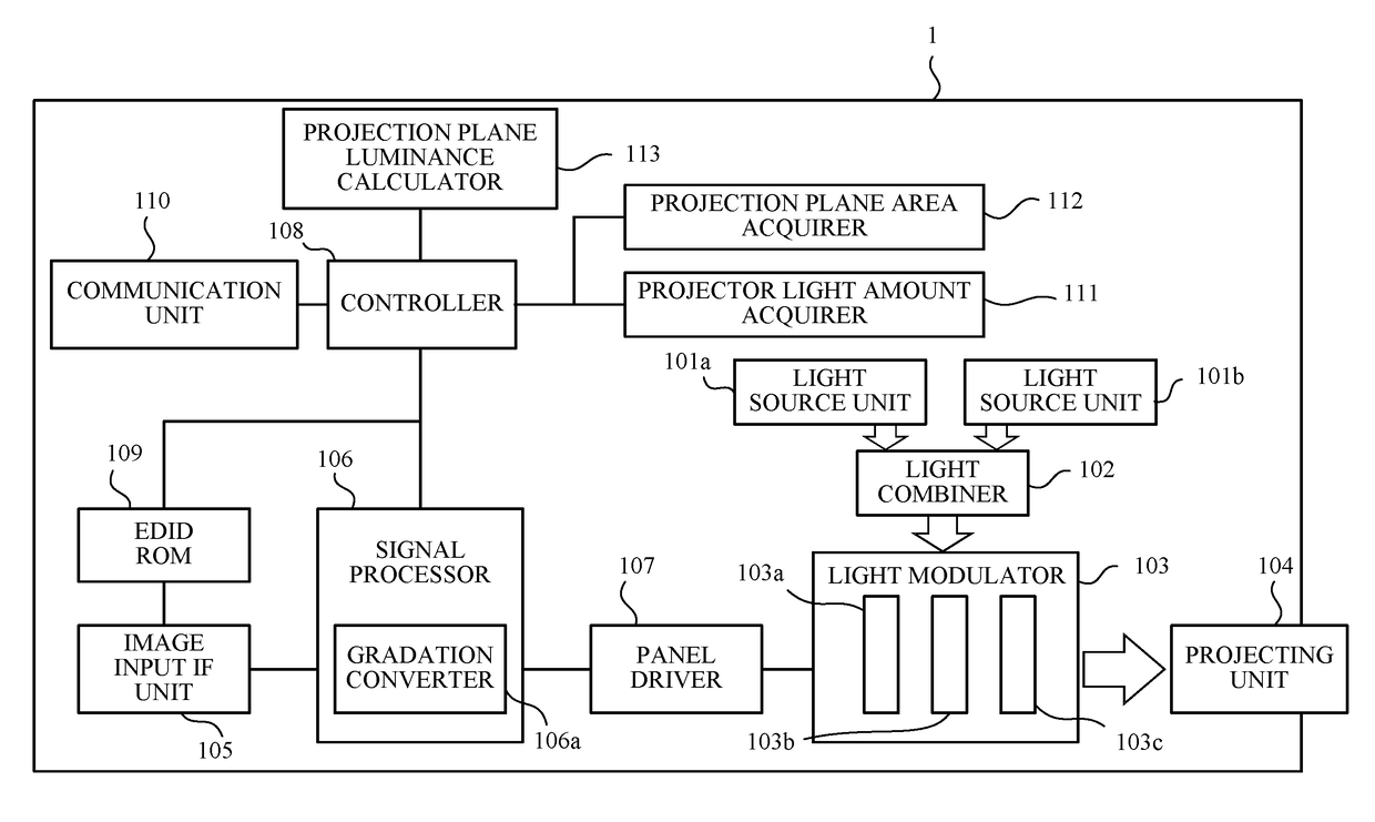
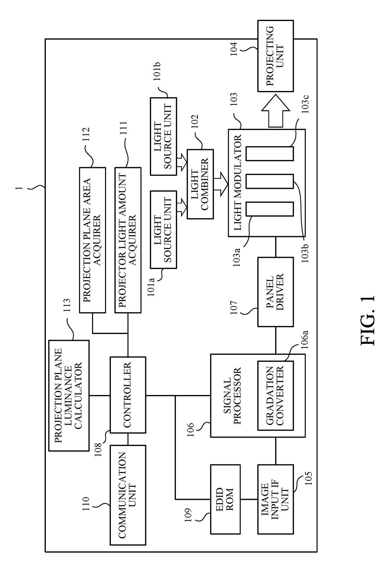
[0021]Referring now to FIG. 1, a description will be given of a projector (projection display apparatus) according to a first embodiment of the present invention. FIG. 1 is a block diagram of a projector 1 according to this embodiment.
[0022]The projector 1 includes light source units 101a and 101b each includes a light source). The projector 1 includes two light source units 101a and 101b in this embodiment, but may include three or more light source units. The light source may use a discharge lamp, such as an ultrahigh pressure mercury lamp. Of course, this embodiment is not limited to this embodiment, and may use a light source other than the discharge lamp, such as a laser or another solid-state light source.
[0023]Light emitted from each of the light source units 101a and 101b is combined by the light combiner 102. The light combiner 102 includes a variety of optical elements, such as a mirror, a prism, and a lens. The light combined by the light combiner 102 enters the light mod...
second embodiment
[0045]Referring now to FIG. 4, a description will be given of a projector (projection display apparatus) according to a second embodiment of the present invention. FIG. 4 is a block diagram of the projector 1A according to this embodiment. Those elements in this embodiment, which are corresponding elements in the first embodiment (FIG. 1), will be designated by the same reference numerals and a description thereof will be omitted.
[0046]This embodiment in which a projection plane luminance calculator 113A calculates the luminance (projection plane luminance) based on the image (projection plane image) captured by a projection plane image capturer 114 is different from the first embodiment in which the projection plane luminance calculator 113 calculates the luminance based on the projection plane area and the projector light amount. In this embodiment, the projection plane image capturer 114 (light amount measuring unit or image capturer) captures an image projected on the projection...
third embodiment
[0051]Referring now to FIG. 5, a description will be given of a projector system (projection display system) according to a third embodiment of the present invention. FIG. 5 is a block diagram of a projector system 100 according to this embodiment. Those elements in this embodiment, which are corresponding elements in the projector 1 according to the first embodiment (FIG. 1), will be designated by the same reference numerals and a description thereof will be omitted.
[0052]The projector system 100 includes a projector 1B (first projection display apparatus), and a projector 2B (second projection display apparatus). The projectors 1B and 2B have the same configurations, but may have different configurations. The projector system 100 according to this embodiment may include the projectors 1B and 2B in a stack state, and project images.
[0053]The projector 1B includes a light source unit 101 (one light source unit) that includes a light source, but may include a plurality of light sourc...
PUM
 Abstract
Description
Claims
Application Information
 - R&D
- Intellectual Property
- Life Sciences
- Materials
- Tech Scout
- Unparalleled Data Quality
- Higher Quality Content
- 60% Fewer Hallucinations
Browse by: Latest US Patents, China's latest patents, Technical Efficacy Thesaurus, Application Domain, Technology Topic, Popular Technical Reports.
© 2025 PatSnap. All rights reserved.Legal|Privacy policy|Modern Slavery Act Transparency Statement|Sitemap|About US| Contact US: help@patsnap.com


