
System for actuating a control surface of an aircraft

a control surface and aircraft technology, applied in the direction of power amplification, servomotors, operating means/releasing devices of valves, etc., can solve the problems of not being able to alleviate load and insufficient architecture, and achieve the effect of reducing load

Active Publication Date: 2019-08-20
AIRBUS OPERATIONS (SAS)
View PDF12 Cites 9 Cited by
  • Summary
  • Abstract
  • Description
  • Claims
  • Application Information

AI Technical Summary

Benefits of technology

[0009]The present invention has an object of remedying this drawback by proposing a system with which it is possible to simultaneously actuate a control surface and alleviate the load on this control surface and its support structure.
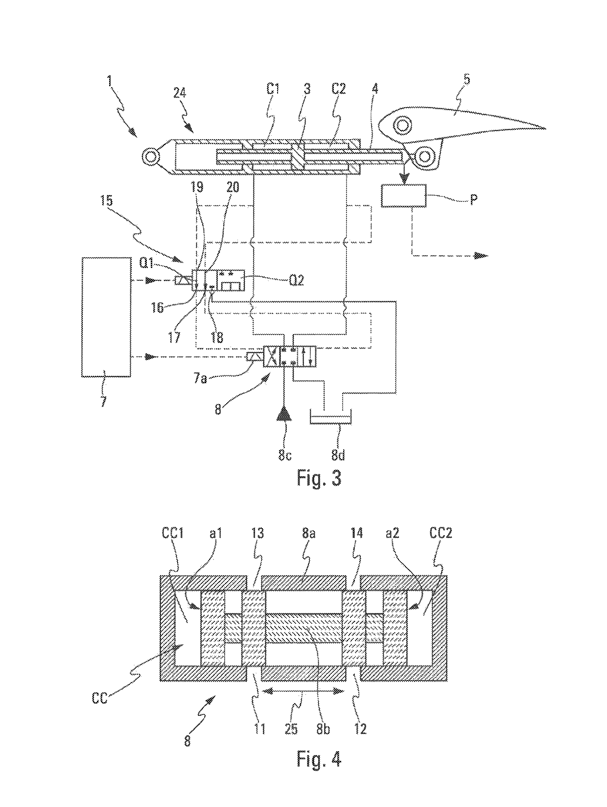
[0014]Thus, by virtue of the fluidic connections between the actuating chambers of the hydraulic actuator and the command chambers of the servo valve, it is possible to simultaneously actuate the control surface of the aircraft and alleviate the load on the control surface, as stated above, and thus to remedy the aforementioned drawback.
[0023]According to one embodiment, the first servo valve comprises a damping unit that is able to damp the sliding motion of the first slider in the sheath of the first servo valve.

Problems solved by technology

However, these valves do not make it possible to alleviate the load in the maneuver, turbulence or gust situations used for designing the plane.
Therefore, this architecture is not entirely satisfactory.

Method used


Image

  • System for actuating a control surface of an aircraft
  • System for actuating a control surface of an aircraft
  • System for actuating a control surface of an aircraft

Examples


Embodiment Construction

[0044]The remainder of the description will refer to the above-mentioned figures.

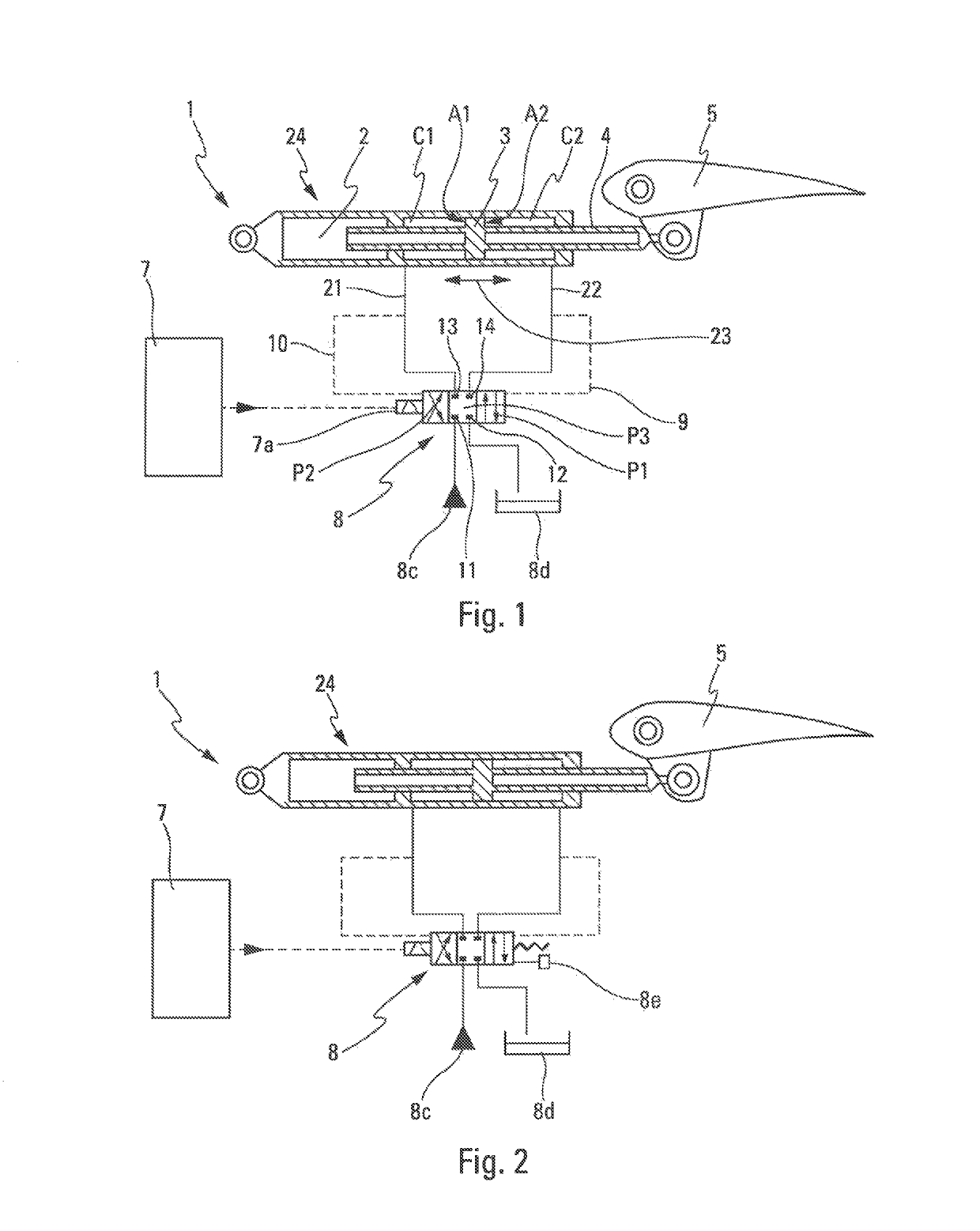
[0045]The invention relates to a system 1 for actuating a control surface 5 of an aircraft AC, installed in the aircraft AC.

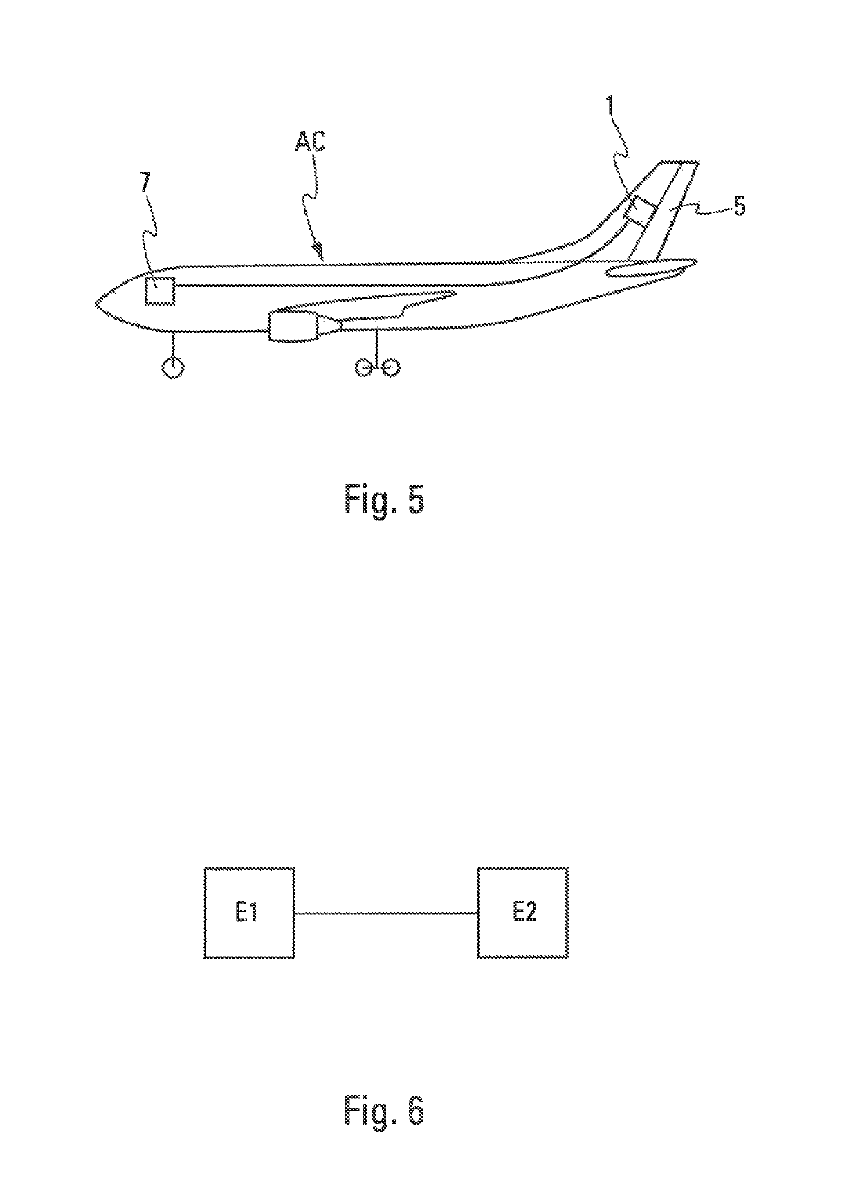
[0046]The actuating system 1 can be applied to any type of control surface 5, in particular the rudder of the aircraft AC, as shown in FIG. 5.

[0047]The actuating system 1, which is shown in FIGS. 1 and 2 and is installed in the aircraft AC, comprises a hydraulic actuator 24. In the remainder of the description, the hydraulic actuator 24 is referred to as the “actuator.” The actuator 24 contains a cylindrical cavity 2 in which a piston 3 is able to slide. The piston 3 separates the cylindrical cavity 2 into a first actuating chamber C1 and a second actuating chamber C2. A pressure difference between the actuating chambers C1 and C2 allows the piston 3 to move. A rod 4 can transmit a movement, illustrated by a double arrow 23 in FIG. 1, from the piston 3 to the control surface 5.

[004...


PUM


Abstract

An actuating system comprising a hydraulic actuator provided with a cylindrical cavity containing a piston configured to slide within the cylindrical cavity and a rod. The piston separates the cylindrical cavity into a first actuating chamber and a second actuating chamber. A first servo valve comprises a sheath including a first slider configured to slide within a cavity of the sheath on the basis of command signals from a command system. The cavity of the sheath comprises a first command chamber and a second command chamber on either side of the first slider. The first actuating chamber is fluidically connected to the first command chamber, and the second actuating chamber is fluidically connected to the second command chamber.

Description

CROSS-REFERENCES TO RELATED APPLICATIONS[0001]This application claims the benefit of the French patent application No. 1657095 filed on Jul. 25, 2016, the entire disclosures of which are incorporated herein by way of reference.TECHNICAL FIELD[0002]The present invention relates to a system for actuating a control surface of an aircraft, such as an aileron, a flap, an elevator or a rudder. This actuating system also has the object of alleviating the load on the control surface and on its support structure.BACKGROUND OF THE INVENTION[0003]There are various systems for actuating a control surface of an aircraft. There are also systems with which it is possible to alleviate the load to which such a control surface is subjected.[0004]Various load alleviation strategies are known. Active load alleviation may be effected for low-frequency side wind perturbations on a vertical tail plane (or VTP) of an aircraft. This load alleviation may be effected using measurements of these perturbations ...

Claims


Application Information

Patent Timeline
Patent Type & Authority Patents(United States)
IPC IPC(8): B64C13/40F16K11/07F15B13/044F15B13/00F15B13/01F15B11/10F16K31/04F16K47/00F15B13/04
CPCB64C13/40F15B11/10F15B13/00F15B13/01F15B13/0402F15B13/0407F16K11/07F16K31/04F16K47/00F15B13/044F15B2211/7053F15B9/12F15B11/08F15B2211/30525F15B2211/32
Inventor BLANC, SÉBASTIENQUIROZ-HERNANDEZ, ESTEBANVERNAY, ROBIN
Owner AIRBUS OPERATIONS (SAS)
Learn More