Energy storage apparatus

a technology of energy storage and equipment, applied in the direction of sustainable manufacturing/processing, cell components, batteries, etc., can solve the problems of condensed dew touching electric equipment and and achieve the effect of suppressing short-circuiting of electric equipmen

Active Publication Date: 2019-08-20
GS YUASA INT LTD
View PDF61 Cites 0 Cited by
  • Summary
  • Abstract
  • Description
  • Claims
  • Application Information

AI Technical Summary

Benefits of technology

[0006]An object of the present invention to provide an energy storage apparatus which can suppress short-circuiting of electric equipment caused by condensed dew generated in an outer covering.

Problems solved by technology

In this case, there is a possibility that the condensed dew touches electric equipment and short-circuiting of the electric equipment occurs.

Method used


Image

  • Energy storage apparatus
  • Energy storage apparatus
  • Energy storage apparatus

Examples


embodiment

[0049]First, a configuration of an energy storage apparatus 1 is described.

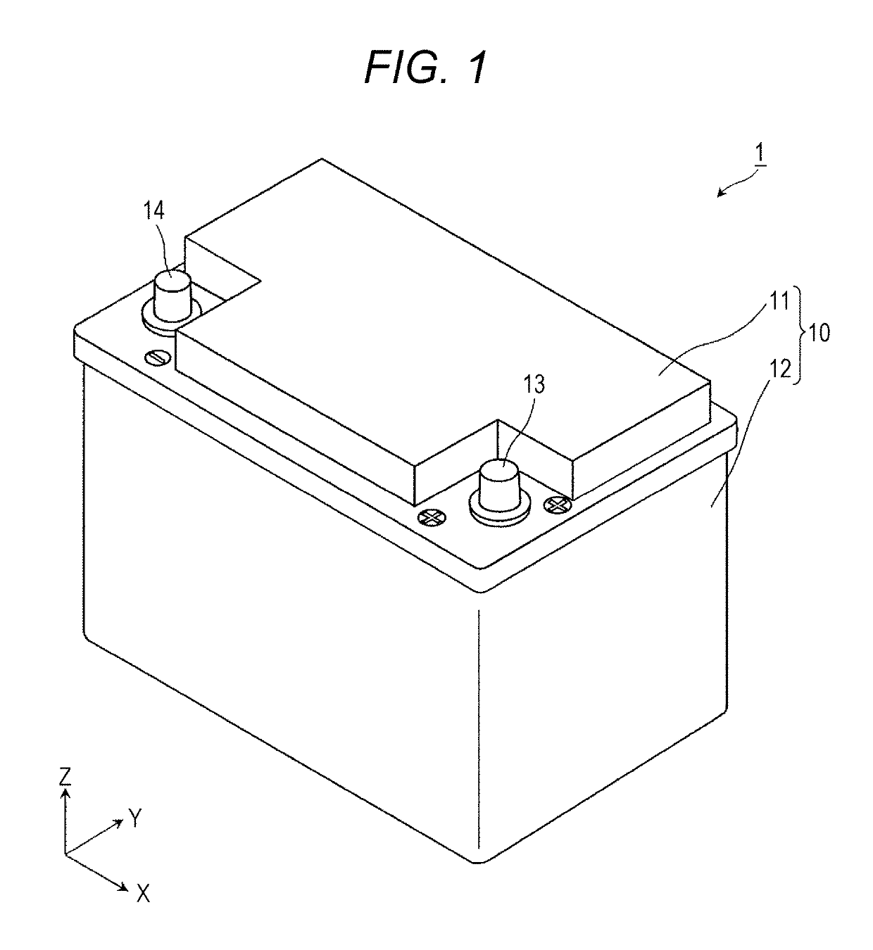
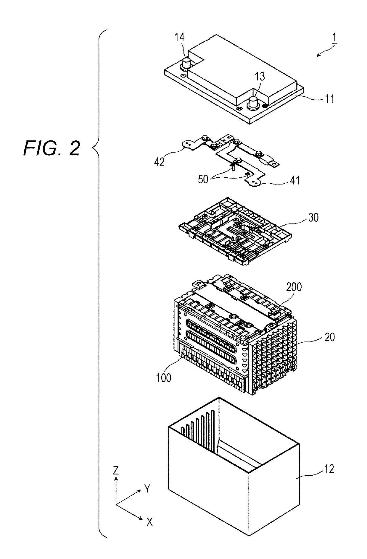
[0050]FIG. 1 is a perspective view showing an external appearance of an energy storage apparatus 1 according to an embodiment of the present invention. FIG. 2 is an exploded perspective view showing constitutional elements of the energy storage apparatus 1.

[0051]In these drawings, the Z axis direction is indicated as the vertical direction, and the description is made hereinafter using the Z axis direction as the vertical direction. However, there may be also a case where the Z axis direction is not the vertical direction depending on a mode of use. Accordingly, the Z axis direction is not limited to the vertical direction. The same goes for drawings which are referenced hereinafter.

[0052]The energy storage apparatus 1 is an apparatus which can charge electricity from the outside of the energy storage apparatus 1 therein or can discharge electricity to the outside of the energy storage apparatus 1. For exampl...

modification 1

(Modification 1)

[0149]Next, a modification 1 of the above-mentioned embodiment is described. In the above-mentioned embodiment, the case is described where, in the grid portion 95, the first wall bodies 951 in the condensation countermeasure region 970 form the first inclined portions. However, the first inclined portion may have any shape as long as the first inclined portion is gradually lowered as the first inclined portion extends toward the edge of the condensation countermeasure region 970.

[0150]Hereinafter, a case where the first inclined portion is a flat surface is described with reference to FIG. 9 and FIG. 10. In the description made hereinafter, parts identical with the parts of the above-mentioned embodiment are given the same symbols and their repeated description is omitted.

[0151]FIG. 9 is a cross-sectional view of a first outer covering 11A according to the modification 1, and is a view which corresponds to FIG. 7. FIG. 10 is a cross-sectional view of the first outer...


PUM

PropertyMeasurementUnit
areaaaaaaaaaaa
hydrophobicaaaaaaaaaa
hydrophilicaaaaaaaaaa

Abstract

An energy storage apparatus including: an energy storage device; an outer covering; electric equipment disposed in the outer covering; and a housing part which houses the electric equipment, wherein a drain passage, which is disposed in a region covered by the electric equipment and through which water is discharged to outside of the region, is formed on a lower wall surface below the electric equipment in the housing part.

Description

CROSS-REFERENCE TO RELATED APPLICATIONS[0001]This application claims the benefit of Japanese patent applications No. 2015-186042, filed on Sep. 18, 2015, and No. 2015-186051, filed on Sep. 18, 2015, which are incorporated by reference.FIELD[0002]The present invention relates to an energy storage apparatus provided with an energy storage device and an outer covering.BACKGROUND[0003]Conventionally, there has been known an energy storage apparatus which houses a plurality of energy storage devices therein. In an outer covering, electric equipment such as a printed circuit board which performs an electric control of the energy storage apparatus is also housed (see JP-2015-11956A, for example).[0004]During the use of an energy storage apparatus, due to a difference in temperature between the inside and outside of an outer covering, there may be a case where dew condensation occurs in the outer covering. In this case, there is a possibility that the condensed dew touches electric equipmen...

Claims


Application Information

Patent Timeline
Patent Type & Authority Patents(United States)
IPC IPC(8): H01M10/42H01M2/04H01M2/02H01M2/36H01M2/30H01M2/12H01M10/04H01M2/10H01M50/209H01M50/227H01M50/264H01M50/278H01M50/284H01M50/293H01M50/296H01M50/60
CPCH01M2/0237H01M2/043H01M2/1252H01M2/30H01M2/1094H01M2200/00H01M10/4207H01M50/60H01M50/227H01M50/264H01M50/278H01M10/658H01M50/296H01M50/284H01M50/293H01M50/209Y02E60/10H01M50/24Y02P70/50
Inventor TONONISHI, MASAMITSU
Owner GS YUASA INT LTD
Why Eureka
Try Eureka