Electric storage device

a technology of electric storage and electrode body, which is applied in the manufacture of cell components, final product details, cell components, etc., can solve the problems of short circuit between the electrode body and the protective, and the protection lead that is not in contact with the joining device may warp, and achieve the effect of high reliability

Active Publication Date: 2021-08-10
SANYO ELECTRIC CO LTD +1
View PDF2 Cites 0 Cited by
  • Summary
  • Abstract
  • Description
  • Claims
  • Application Information

AI Technical Summary

Benefits of technology

[0008]It is therefore an object of the present invention to provide an electric storage device having current collecting tabs and a protective lead that are joined together with higher reliability.
[0010]According to the present disclosure, warping of the protective sheet caused when the tab is joined to the current collector together with the protective sheet is suppressed, and it is possible to suppress short-circuiting due to contact between the protective sheet and the electrode body.

Problems solved by technology

However, when joining is performed by pressing a joining device such as an ultrasonic joining device against the current collecting tabs with the protective lead therebetween, a part of the protective lead that is not in contact with the joining device may warp in the direction away from the current collecting tabs.
When the distance between the joint of the protective lead and the electrode body is reduced in order to reduce the empty space in the outer casing, this warpage may cause a short circuit between the electrode body and the protective lead.

Method used


Image

  • Electric storage device
  • Electric storage device
  • Electric storage device

Examples


embodiments

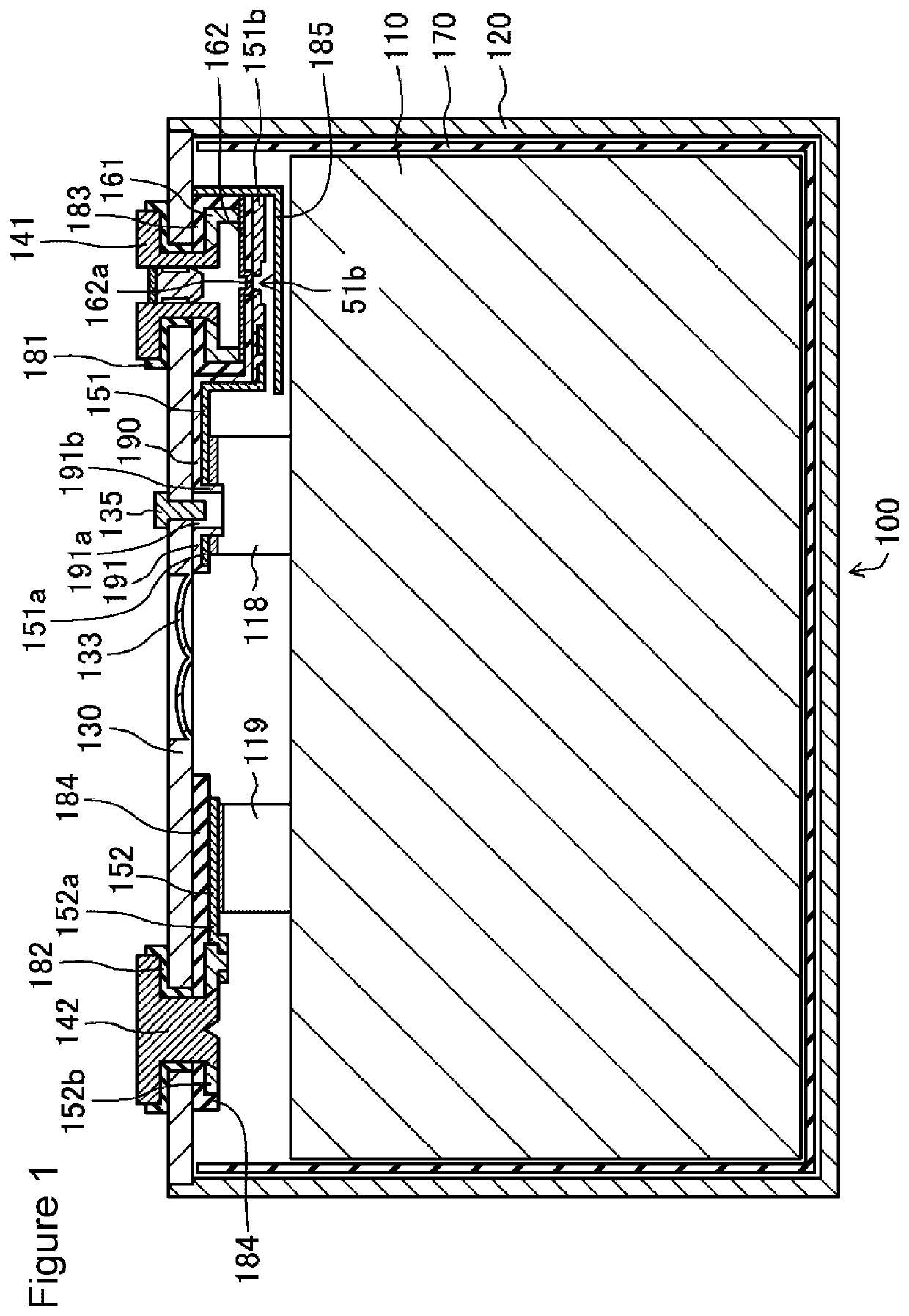
[0024]FIG. 1 is a cross-sectional view of an electric storage device 100 according to an embodiment of the present invention. As shown in FIG. 1, the electric storage device 100 includes an electrode body 110 including positive electrode plates, negative electrode plates, and separators, a bottomed prismatic outer casing 120 accommodating the electrode body 110 and having an opening, and a lid 130 sealing the opening of the outer casing 120.

[0025]The outer casing 120 and the lid 130 are each preferably made of metal, for example, aluminum or aluminum alloy. The electrode body 110 includes a plurality of positive electrode plates and a plurality of negative electrode plates stacked alternately with separators therebetween. The electrode body 110 is accommodated in the outer casing 120 together with electrolyte (not shown). An insulating sheet 170 is interposed between the electrode body 110 and the outer casing 120.

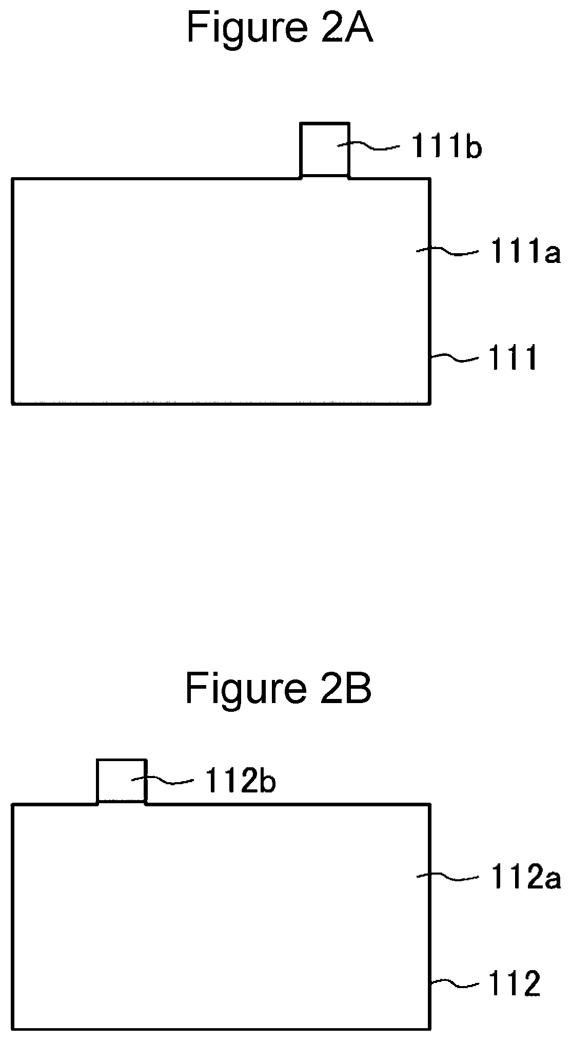
[0026]FIG. 2A is a plan view showing a positive electrode plate (firs...


PUM

PropertyMeasurementUnit
thicknessaaaaaaaaaa
thicknessaaaaaaaaaa
thicknessaaaaaaaaaa

Abstract

An electric storage device includes an electrode body including a plurality of first electrode plates and a plurality of second electrode plates, a first electrode output terminal, a second electrode output terminal, a first current collector, and a second current collector. The first electrode plates have first tabs that protrude from the electrode body and have conductivity and are connected to the first current collector. The first tabs are stacked to form a first tab stack, one surface of the first tab stack is in contact with the first current collector, and a first protective sheet is disposed on and in contact with the other surface on the side opposite to the one surface. On the periphery of the first protective sheet, there is a corner formed by two adjacent sides. At least the corner of the first protective sheet is joined to the first tab stack.

Description

CROSS REFERENCE TO RELATED APPLICATIONS[0001]The present invention application claims priority to Japanese Patent Application No. 2018-065041 filed in the Japan Patent Office on Mar. 29, 2018, the entire contents of which are incorporated herein by reference.BACKGROUND OF THE INVENTIONField of the Invention[0002]The present invention relates to an electric storage device.Description of Related Art[0003]Electric storage devices are used as power sources for driving electric vehicles (EV) and hybrid electric vehicles (HEV and PHEV), as well as for electronic devices. As the electric storage device, for example, an alkaline secondary battery or a nonaqueous electrolyte secondary battery is used.[0004]These electric storage devices include, for example, an electrode body including a positive electrode plate, a negative electrode plate, and a separator, an outer casing accommodating the electrode body, a lid covering the opening of the outer casing, an electrode terminal connected to one...

Claims


Application Information

Patent Timeline
Patent Type & Authority Patents(United States)
IPC IPC(8): H01M2/26H01M10/04H01M50/54H01M50/533
CPCH01M50/54H01M10/0413H01M50/533Y02E60/10Y02P70/50
Inventor TAKABAYASHI, HIROSHINAKATA, NAOFUMI
Owner SANYO ELECTRIC CO LTD
Why Eureka
Try Eureka