Control device for wire electrical discharge machine and control method of wire electrical discharge machine

Active Publication Date: 2018-12-20
FANUC LTD
View PDF2 Cites 0 Cited by
  • Summary
  • Abstract
  • Description
  • Claims
  • Application Information

AI Technical Summary

Benefits of technology

The invention prevents short-circuiing between the wire electrode and the workpiece.

Problems solved by technology

Since, in finishing mode, a discharge voltage applied across a gap between the wire electrode and the workpiece is smaller than that in rough machining mode while the gap between the wire electrode and the workplace is narrow, the average voltage is liable to fall sharply.
Therefore, before the wire electrode is moved back from the workpiece, the wire electrode is prone to touch the workpiece, causing a short-circuit problem.

Method used


Image

  • Control device for wire electrical discharge machine and control method of wire electrical discharge machine
  • Control device for wire electrical discharge machine and control method of wire electrical discharge machine
  • Control device for wire electrical discharge machine and control method of wire electrical discharge machine

Examples


first embodiment

[Configuration of Wire Electrical Discharge Machine and Control Device]

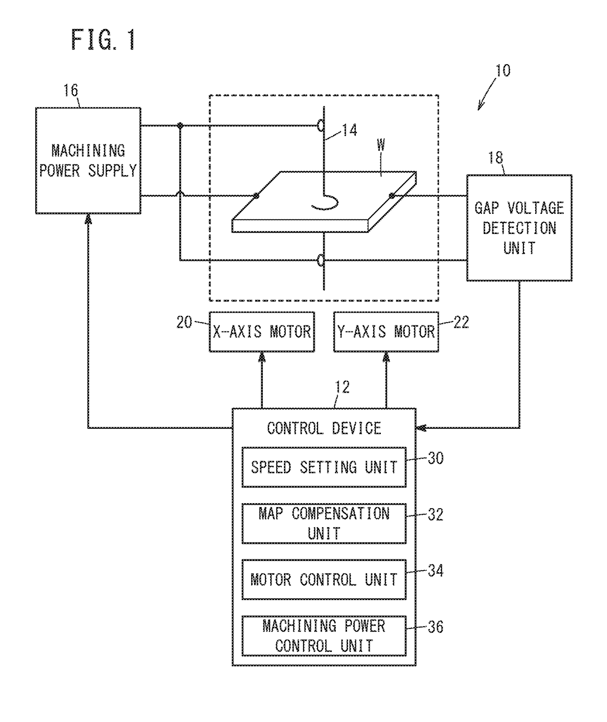
[0026]FIG. 1 is a schematic diagram showing a configuration of a wire electrical discharge machine 10 and a control device 12 for controlling the wire electrical discharge machine 10. The wire electrical discharge machine 10 is a machine tool that generates electrical discharge by applying voltage across an electrode gap formed between a wire electrode 14 and a workpiece W to thereby perform electrical discharge machining on the workpiece W. The wire electrode 14 is made of, for example, metal material such as tungsten-based, copper alloy-based, and brass-based material. On the other hand, the workplace W is made of, for example, an iron-based material, a superhard material (e.g., tungsten carbide), or the like. The wire electrical discharge machine 10 includes a machining power supply 16 for applying voltage between the wire electrode 14 and the workpiece W, and an gap voltage detection unit 18 for detecting the...

modification 1

[Modification 1]

[0046]In the first embodiment, the relative speed command value is set according to the average gap voltage. However, the reciprocal of the number of discharge pulses per unit time may be used instead of the average gap voltage. Since the frequency of discharge pulses increases as the gap distance decreases, the gap distance and the number of discharge pulses per unit time are highly correlated so that the reciprocal of the number of discharge pulses per unit time may be used in the same manner as the average gap voltage. In this case, as shown in FIG. 10, the number of discharge pulses is detected by using a discharge pulse counting unit 24 instead of the gap voltage detection unit 18 of the first embodiment.

modification 2

[Modification 2]

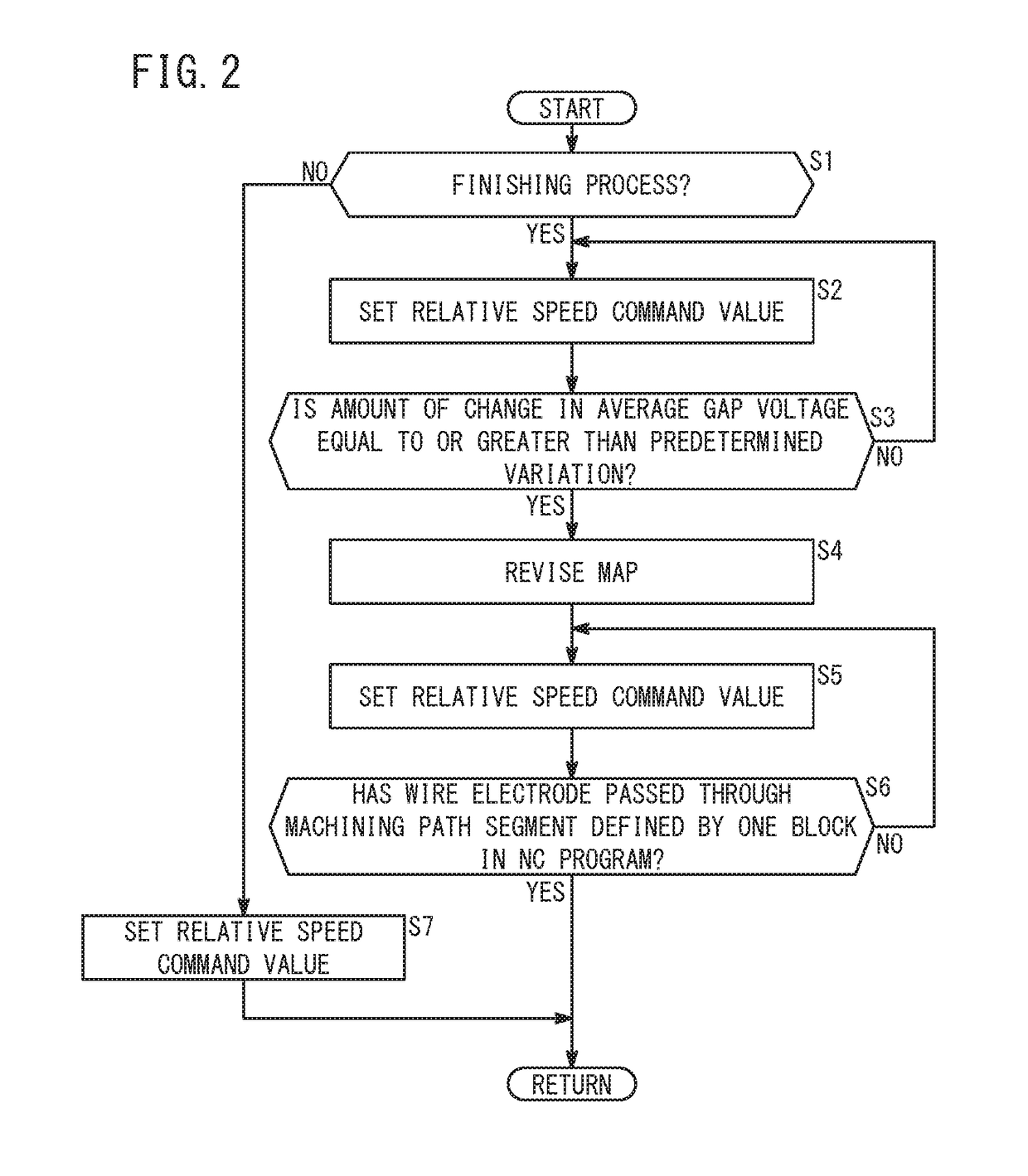
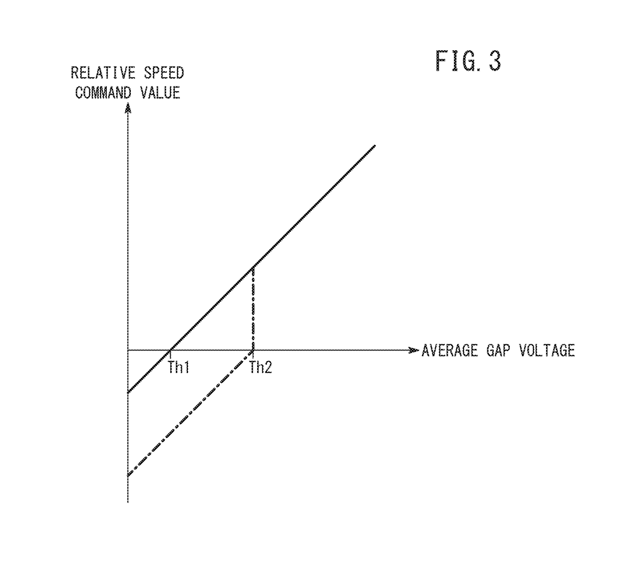
[0047]As described above, the relationship between the gap distance and the average gap voltage tends to become unstable when the wire electrode 14 machines the inner side of a circular arc. To deal with this, in a machining path segment defined by a block having a predetermined command code (e.g., G02 or G03) in the NC program, when the average gap voltage changes in a decreasing direction and the amount of change in the average gap voltage becomes equal to or greater than a predetermined variation, the backward-movement threshold may be revised to the second threshold Th2 greater than the first threshold Th1.

[0048]Even on a linear machining path segment, there are cases in which the amount of change in the average gap voltage becomes equal to or greater than a predetermined variation. However, the average gap voltage is less likely to fall sharply thereafter. In this case, if the backward-movement threshold is set to the second threshold Th2, the frequency of the w...


PUM

PropertyMeasurementUnit
Speedaaaaaaaaaa
Threshold limitaaaaaaaaaa

Abstract

A control device includes a speed setting unit configured to set a relative movement speed of a wire electrode with respect to a workpiece depending on the average of gap voltage per unit time, i.e., average gap voltage, and set the relative movement speed so as to move the wire electrode backward when the average gap voltage is less than a threshold, and a map compensation unit configured to change the threshold from a first threshold that is set when the amount of change in the average gap voltage is lower than a predetermined variation, to a second threshold that is greater than the first threshold, when the average gap voltage has changed in a decreasing direction and the amount of change in the average gap voltage becomes equal to or greater than the predetermined variation.

Description

CROSS-REFERENCE TO RELATED APPLICATION[0001]This application is based upon and claims the benefit of priority from Japanese Patent Application No. 2017-119373 filed on Jun. 19, 2017, the contents of which are incorporated. herein by reference.BACKGROUND OF THE INVENTION[0002]Field of the Invention[0003]The present invention relates to a control device for a wire electrical discharge machine and a method of controlling the wire electrical discharge machine, in which a wire electrode is moved relatively to a workpiece to perform electrical discharge machining on the workpiece with the wire electrode.[0004]Description of the Related Art[0005]Japanese Laid-Open Patent Publication No. 2003-165031 discloses a machine that is adapted to move a wire electrode backward from a workpiece when the average voltage between the wire electrode and the workpiece becomes lower than a short-circuit reference voltage.SUMMARY OF THE INVENTION[0006]Since, in finishing mode, a discharge voltage applied ac...

Claims


Application Information

Patent Timeline
IPC IPC(8): B23H7/20B23H7/18B23H7/32G05B19/19
CPCB23H7/20B23H7/18B23H7/32G05B19/19G05B2219/45221G05B2219/42249B23H7/02B23H7/04B23H7/16G05B2219/45043B23H1/02B23H2600/00
Inventor NISHIKAWA, RYOU
Owner FANUC LTD
Why Eureka
Try Eureka