Electricity storage device

a technology of electric storage device and separator, which is applied in the direction of sustainable manufacturing/processing, cell components, batteries, etc., can solve the problems of enlarge the separator, interfere with the electrode terminal through the conductive members of the separator, and complicate the manufacture, so as to simplify the manufacturing of the separator and increase the extension contraction amount

Active Publication Date: 2018-07-17
TOYOTA IND CORP
View PDF19 Cites 0 Cited by
  • Summary
  • Abstract
  • Description
  • Claims
  • Application Information

AI Technical Summary

Benefits of technology

[0010]In this configuration, the basal portion of the positive electrode tab is covered by the tab opposing portion of the separator. This limits short-circuiting of the positive electrode tab and the negative electrode. The separator includes the opposing parts located at opposite sides of the tab opposing portion along the side of the separator. The amount of the welded portion extending from the accommodation portion at the opposing parts is less than the amount of the welded portion extending from the accommodation portion at other parts. Thus, at the side of the separator, the opposing parts are located below the tab opposing portion, the opposing parts are separated from the wall, to which the electrode terminal is fixed, more than the tab opposing portion. This limits interference of the electrode terminal with the side of the separator through the conductive member while the tab opposing portion limits short-circuiting of the positive electrode tab. The separator that limits short-circuiting of the positive electrode tab and avoids interference between the electrode terminal and the separator through the conductive member may be formed when forming the opposing parts through thermal welding just by increasing the extension contraction amount compared to other parts. This simplifies the manufacturing of the separator compared to when the separator is cut or the like.

Problems solved by technology

In such a case, the manufacturing is complicated compared to when using the rectangular separator without making any changes.
However, the use of one entire side of the separator as the guard will enlarge the separator.
Further, since one entire side of the separator will be closer to the electrode terminals, the separator may interfere with the electrode terminals through the conductive members.

Method used


Image

  • Electricity storage device
  • Electricity storage device
  • Electricity storage device

Examples


Embodiment Construction

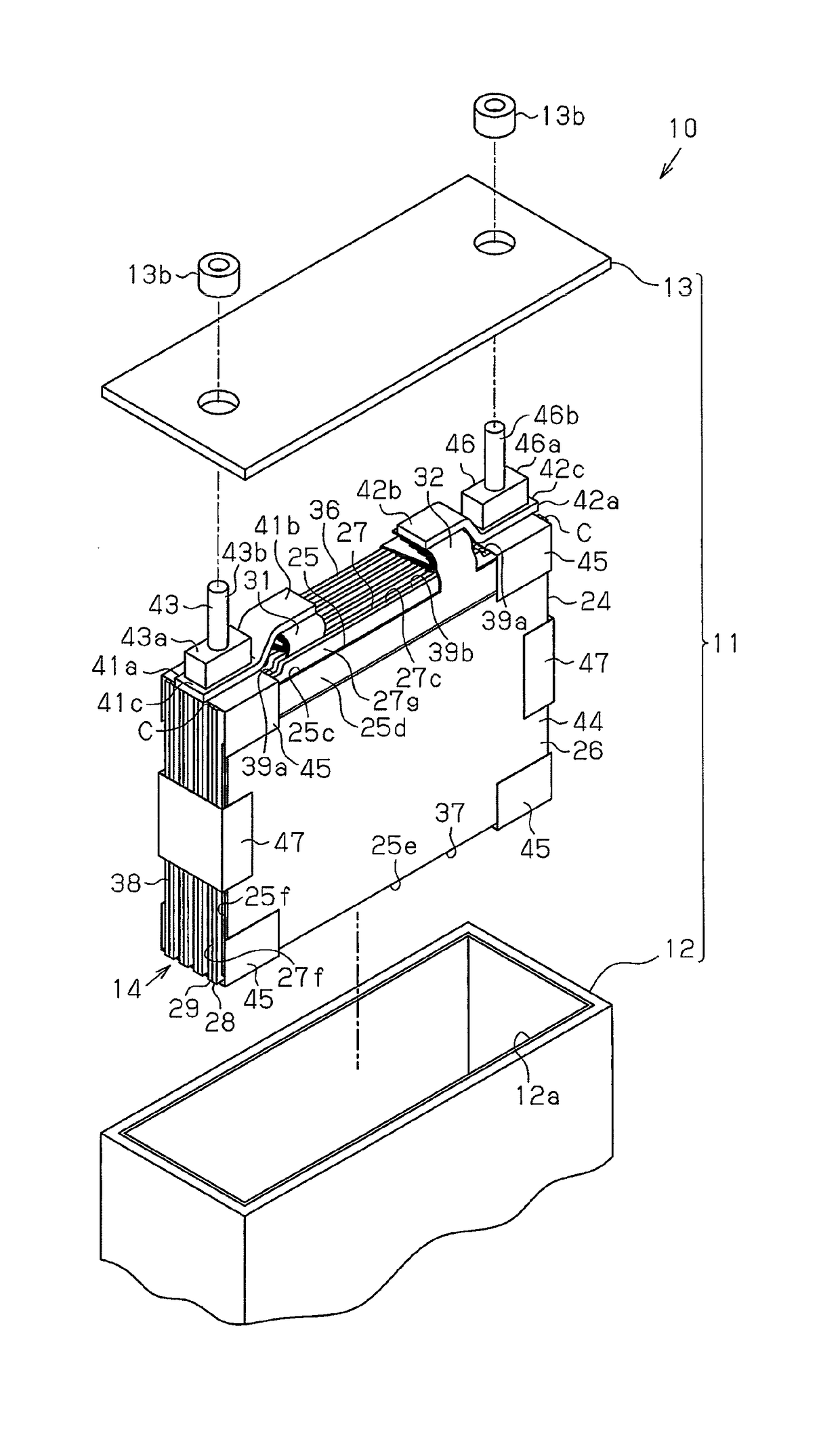
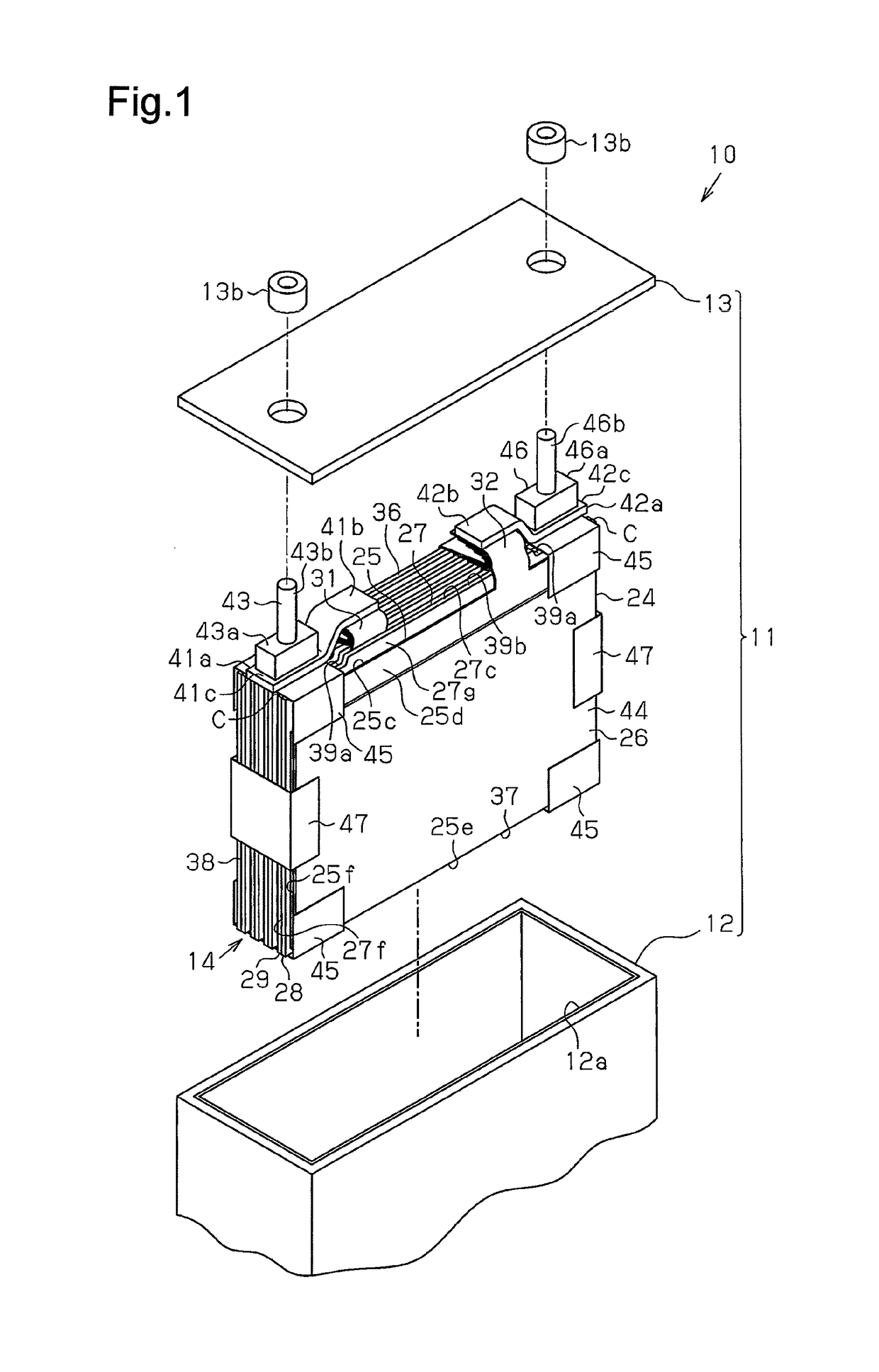
[0023]One embodiment of an electricity storage device, which is embodied in a rechargeable battery, will now be described with reference to FIGS. 1 to 4.

[0024]As shown in FIGS. 1 and 2, a rechargeable battery 10 includes a metal case 11, which defines a shell. The case 11 includes a box-shaped case body 12, which includes an opening 12a in one surface and a closed end, and a cover 13, which closes the opening 12a. The case 11 accommodates an electrode assembly 14 and an electrolytic solution (not shown), which serves as electrolyte. The rechargeable battery 10 is a lithium-ion battery.

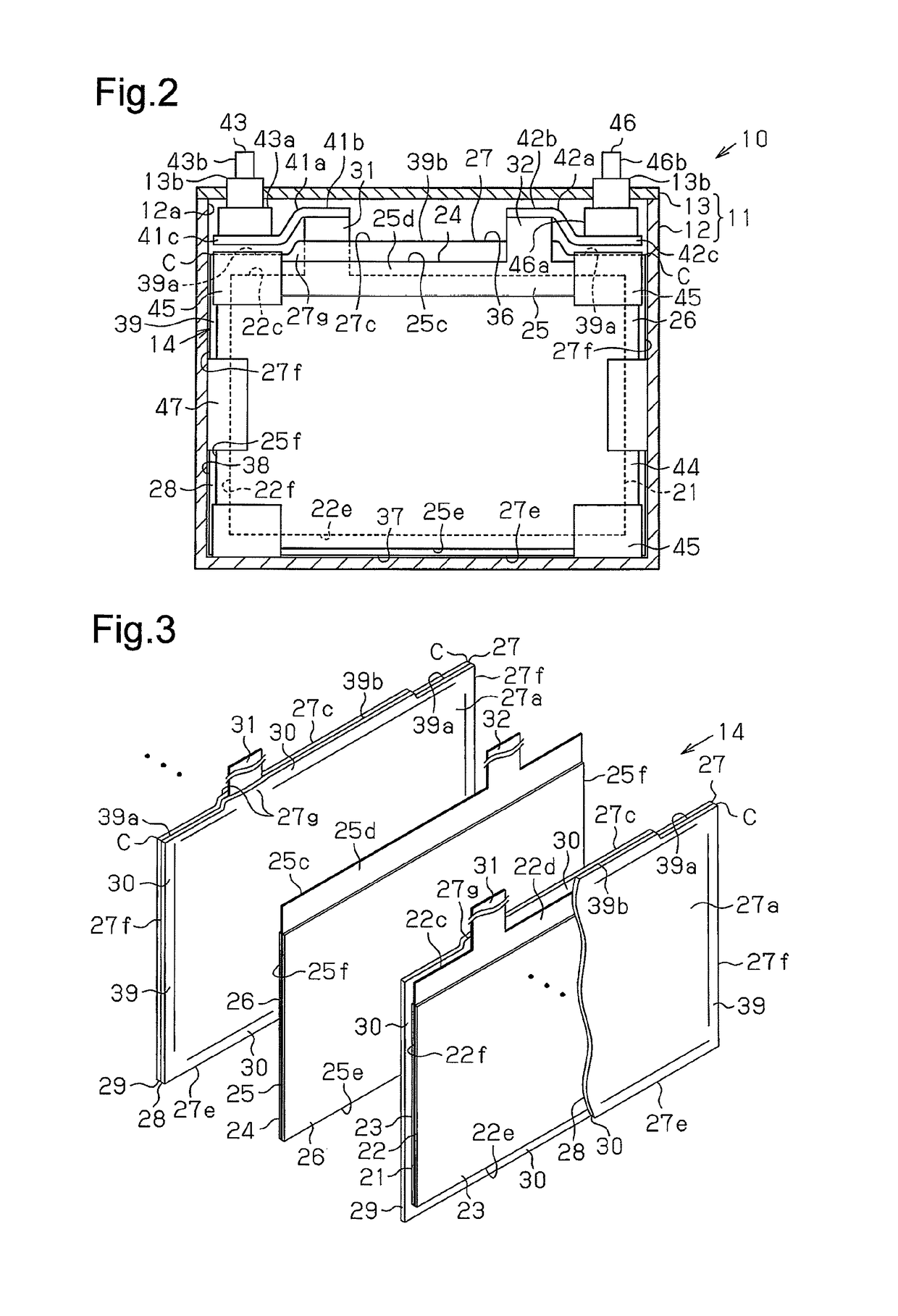
[0025]As shown in FIG. 3, the electrode assembly 14 includes positive electrodes 21, which serve as positive electrodes, negative electrodes 24, which serve as negative electrode, and resin separators 27, which insulate the positive electrodes 21 from the negative electrodes 24. The electrode assembly 14 has a laminated structure in which the positive electrodes 21 and the negative electrodes 24 are al...


PUM

PropertyMeasurementUnit
conductiveaaaaaaaaaa
areaaaaaaaaaaa
current concentrationaaaaaaaaaa

Abstract

This electricity storage device comprises an electrode assembly, a case, an electrode terminal and a conductive member. The electrode assembly comprises a positive electrode, a negative electrode and a separator. The separator comprises a first separator part and a second separator part. The separator has a container part that contains portions of the positive electrode other than a tab. The separator has a welded part and a tab facing part. The welded part has facing parts that are positioned on both sides of the tab facing part. The facing parts face the electrode terminal with the conductive member being interposed therebetween. The facing parts are larger in shrinkage amount associated with thermal welding than the other portions of the welded part.

Description

TECHNICAL FIELD[0001]The present invention relates to an electricity storage device that includes an electrode assembly, which includes positive electrodes, negative electrodes, and resin separators that are alternately stacked, and a case, which accommodates the electrode assembly.BACKGROUND ART[0002]A rechargeable battery that is installed in a vehicle such as an electric vehicle (EV) or a plug in hybrid vehicle (PHV) serves as an electricity storage device that stores power supplied to a travel motor. The rechargeable battery may include an electrode assembly accommodated in a case. The electrode assembly includes sheets of positive electrodes and sheets of negative electrodes that are stacked insulated from one another. Each positive electrode includes positive active material layers applied to opposite surfaces of a positive metal foil. Each negative electrode includes negative active material layers applied to opposite surfaces of a negative metal foil.[0003]In the case, tabs ...

Claims


Application Information

Patent Timeline
Patent Type & Authority Patents(United States)
IPC IPC(8): H01M2/26H01M2/24H01G11/74H01G11/82H01M10/04H01G11/26H01M2/18H01M2/06H01G11/52H01M50/176H01M50/466H01M50/529H01M50/54
CPCH01M2/26H01G11/26H01G11/52H01G11/74H01G11/82H01M2/06H01M2/24H01M2/266H01M10/0413H01M2/18Y02T10/7022H01M2/263H01M2220/20Y02E60/13Y02T10/70Y02E60/10H01M50/54Y02P70/50H01M50/176H01M50/466H01M50/529
Inventor OKUDA, MOTOAKIMINAGATA, ATSUSHIHAMAGUCHI, YOHEI
Owner TOYOTA IND CORP
Why Eureka
Try Eureka