
Metal-air battery and protected lithium electrode used therein

a lithium electrode and metal-air battery technology, which is applied in the direction of fuel and primary cells, cell components, cell component details, etc., can solve the problems of internal short circuit between the cathode and the anode, the risk of deterioration of solid electrolyte, and the decrease of the charging and discharging characteristics of the metal-air battery, so as to prevent the passing of metal fine powder, prevent the effect of metal fine powder passing, and block the effect of metal fine powder

Active Publication Date: 2020-06-09
SUZUKI MOTOR CORP
View PDF12 Cites 0 Cited by
  • Summary
  • Abstract
  • Description
  • Claims
  • Application Information

AI Technical Summary

Benefits of technology

The patent proposes a protected anode structure for metal-air batteries that prevents the anode from being short-circuited and improves charging and discharging cycle characteristics. This structure includes a sack-shaped anode layer wrapped in material that passes lithium ions, such as a separator. This technology can be used in both non-aqueous and aqueous solution-based metal-air batteries. It prevents metal particles from forming fine powder that could damage the battery and cause short circuits.

Problems solved by technology

Thus, there arises a problem that the charging and discharging characteristic of the metal-air battery decreases.
In addition, in a non-aqueous solution-based metal-air battery, when this metal such as Li formed into fine powder reaches the cathode, there may be a risk of internal short circuiting between the cathode and the anode.
On the other hand, in an aqueous solution-based metal-air battery, when the metal such as Li formed into fine powder reaches a solid electrolyte, there may be a risk of deterioration of the solid electrolyte.

Method used


Image

  • Metal-air battery and protected lithium electrode used therein
  • Metal-air battery and protected lithium electrode used therein
  • Metal-air battery and protected lithium electrode used therein

Examples


example

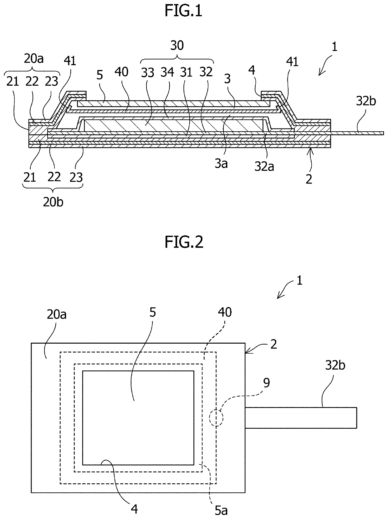
[0092]An aqueous solution-based lithium-air battery employing a protected anode having the same configuration shown in FIG. 1 was fabricated, and a charging and discharging test was carried out on this battery.

[Fabrication of Protected Anode]

[0093]First, as in the case of an Example, a protected anode was fabricated by placing an exterior material which is a PP resin / Al foil / PET resin metal foil laminate film having a center portion punched in 2 square centimeters, an acid-modified polypropylene film punched product (outer peripheral portion: 3 square centimeters; inner periphery: 2 square centimeters), a 2.5-square-centimeter solid electrolyte (LATP), and an acid-modified polypropylene film punched product (outer peripheral portion: 3 square centimeters; inner periphery: 2 square centimeters) in this order. Four sides of the solid electrolyte were joined by heat sealing with a heat sealer to make an upper exterior body.

[0094]The solid electrolyte on the inner side (anode side) of t...


PUM

PropertyMeasurementUnit
thicknessaaaaaaaaaa
thicknessaaaaaaaaaa
porosityaaaaaaaaaa

Abstract

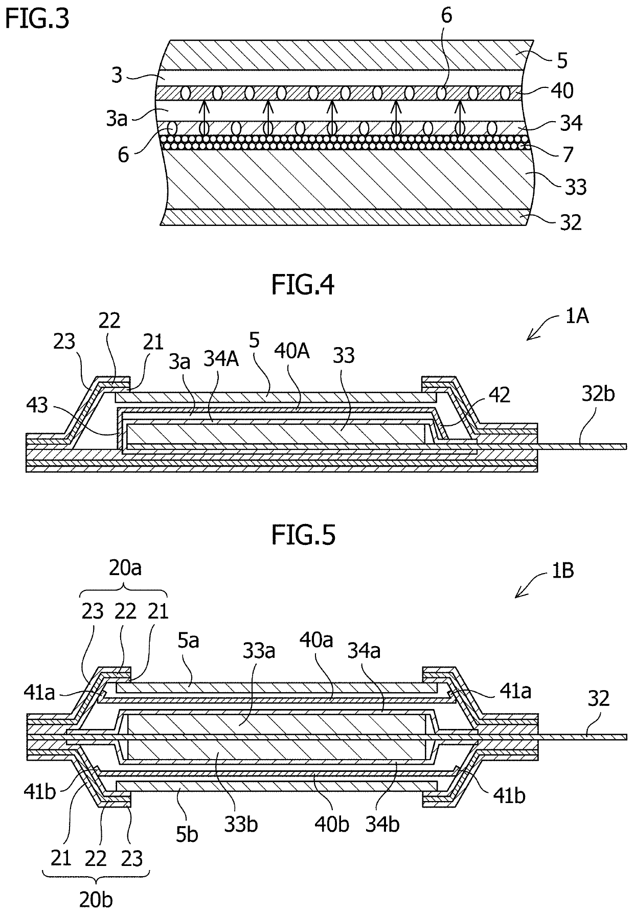
A metal-air battery and a protected anode used therein, which make it possible to prevent the metal such as Li being an anode active material and formed into fine powder from dispersing away from the anode layer, and to improve charging and discharging cycle characteristics, even in the case of a charging and discharging cycle over a long period of time. For example, a protected anode 1 includes an anode current collector 32; an anode layer 33 which is stacked on an air electrode side of the anode current collector and which includes a metal being an anode active material of a metal-air battery; a first separator 34 which is stacked on the air electrode side of the anode layer and which includes multiple pores permeable to ions of the metal and an organic electrolytic liquid; and a second separator 40 which is provided on the air electrode side of the first separator so as to be movable relative to the first separator in an inter-electrode direction and which includes multiple pores permeable to the metal ions and the organic electrolytic liquid. In addition, the protected anode may be used to fabricate a metal-air battery.

Description

CROSS-REFERENCES TO RELATED APPLICATION[0001]The present application claims priority from Japanese Patent Application No. 2017-164226, filed Aug. 29, 2017, the disclosure of which is hereby incorporated herein by reference.TECHNICAL FIELD[0002]The present invention relates to a metal-air battery and a protected lithium electrode used therein.BACKGROUND ART[0003]A metal-air battery uses a metal such as lithium as an anode active material and uses oxygen in the atmosphere as a cathode active material, and is expected, thanks to its high energy density, as a battery capable of obtaining an energy density of 700 Wh / kg required for widespread use and standardization of electric automobiles. This energy density is seven times greater than those of lithium-ion batteries which are presently beginning to be mounted in vehicles.[0004]Patent Document 1 discloses an internal structure of a protected anode of a metal-air battery is provided, as a buffer layer, with a porous resin sheet, for exam...

Claims


Application Information

Patent Timeline
Patent Type & Authority Patents(United States)
IPC IPC(8): H01M2/14H01M4/02H01M12/08H01M50/40H01M50/489H01M50/491
CPCH01M2/14H01M12/08H01M4/02H01M2300/0025H01M4/86H01M12/06H01M50/40H01M50/491H01M50/489Y02E60/10
Inventor IZUMI, HIROAKIMINAMI, HIRONARI
Owner SUZUKI MOTOR CORP
Learn More