
Golf club with movable weight

a golf club and movable technology, applied in the field of golf clubs, can solve the problems of reducing the performance not maximizing the peripheral weight of the golf club head or the moi, and being subject to delamination or corrosion over time, so as to improve the playability improve the performance characteristics of the golf club, and facilitate the movability and rapid movement of the weight

Active Publication Date: 2019-08-27
ACUSHNET CO
View PDF249 Cites 5 Cited by
  • Summary
  • Abstract
  • Description
  • Claims
  • Application Information

AI Technical Summary

Benefits of technology

Enables precise manipulation of the center of gravity and moment of inertia, enhancing playability and distance by allowing golfers to customize the club's performance characteristics easily and securely.

Problems solved by technology

Though the mass characteristics of the golf club may be manipulated by rearranging the moveable weights, the cylindrical shape of the weights and the receiving features within the golf club body necessarily moves a significant portion of the mass toward the center of the club head, which may not maximize the peripheral weight of the club head or the MOI.
Because composite materials like those found in the club head must be bonded together, for example by welding, swaging, or using bonding agents such as epoxy, they may be subject to delamination or corrosion over time.
This component delamination or corrosion results in decreased performance in the golf club head and can lead to club head failure.
One aspect of the present technology is the realization that position of weight elements in existing golf club head designs are not easily adjustable.

Method used


Image

  • Golf club with movable weight
  • Golf club with movable weight
  • Golf club with movable weight

Examples


Embodiment Construction

[0098]In the following detailed description, reference is made to the accompanying drawings, which form a part of the present disclosure. The illustrative embodiments described in the detailed description, drawings, and claims are not meant to be limiting. Other embodiments may be utilized, and other changes may be made, without departing from the spirit or scope of the subject matter presented herein. It will be readily understood that the aspects of the present disclosure, as generally described herein, and illustrated in the Figures, can be arranged, substituted, combined, and designed in a wide variety of different configurations, all of which are explicitly contemplated and form part of this disclosure. For example, a system or device may be implemented or a method may be practiced using any number of the aspects set forth herein. In addition, such a system or device may be implemented or such a method may be practiced using other structure, functionality, or structure and func...


PUM


Abstract

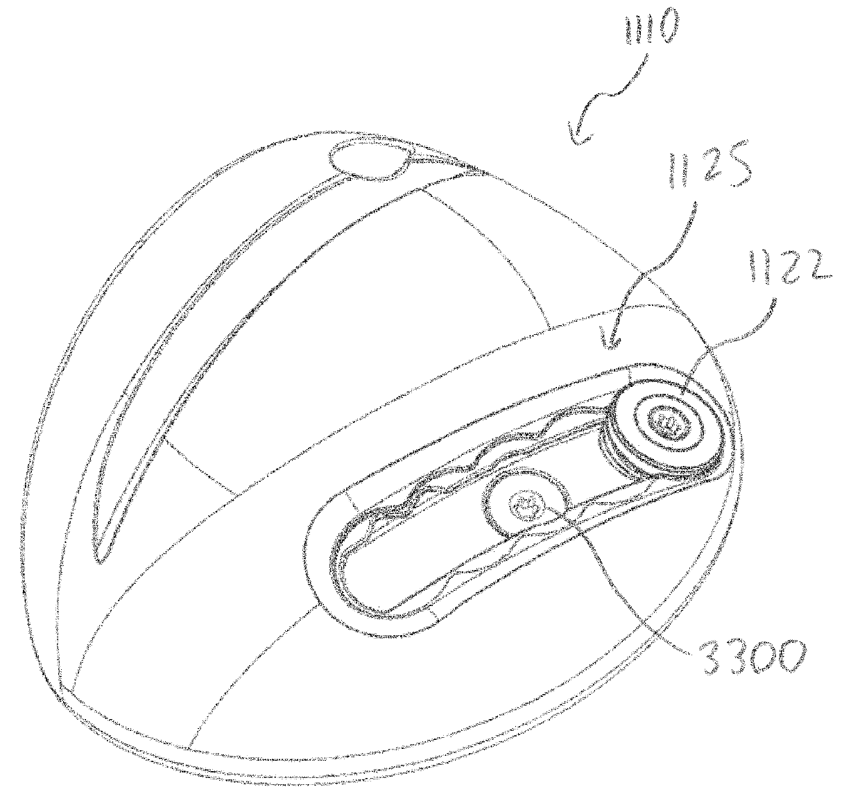
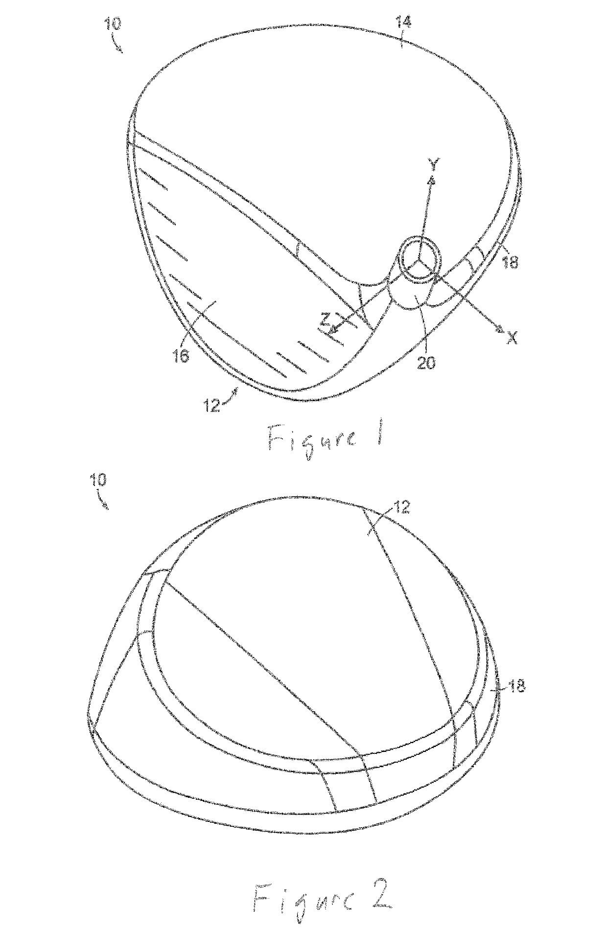
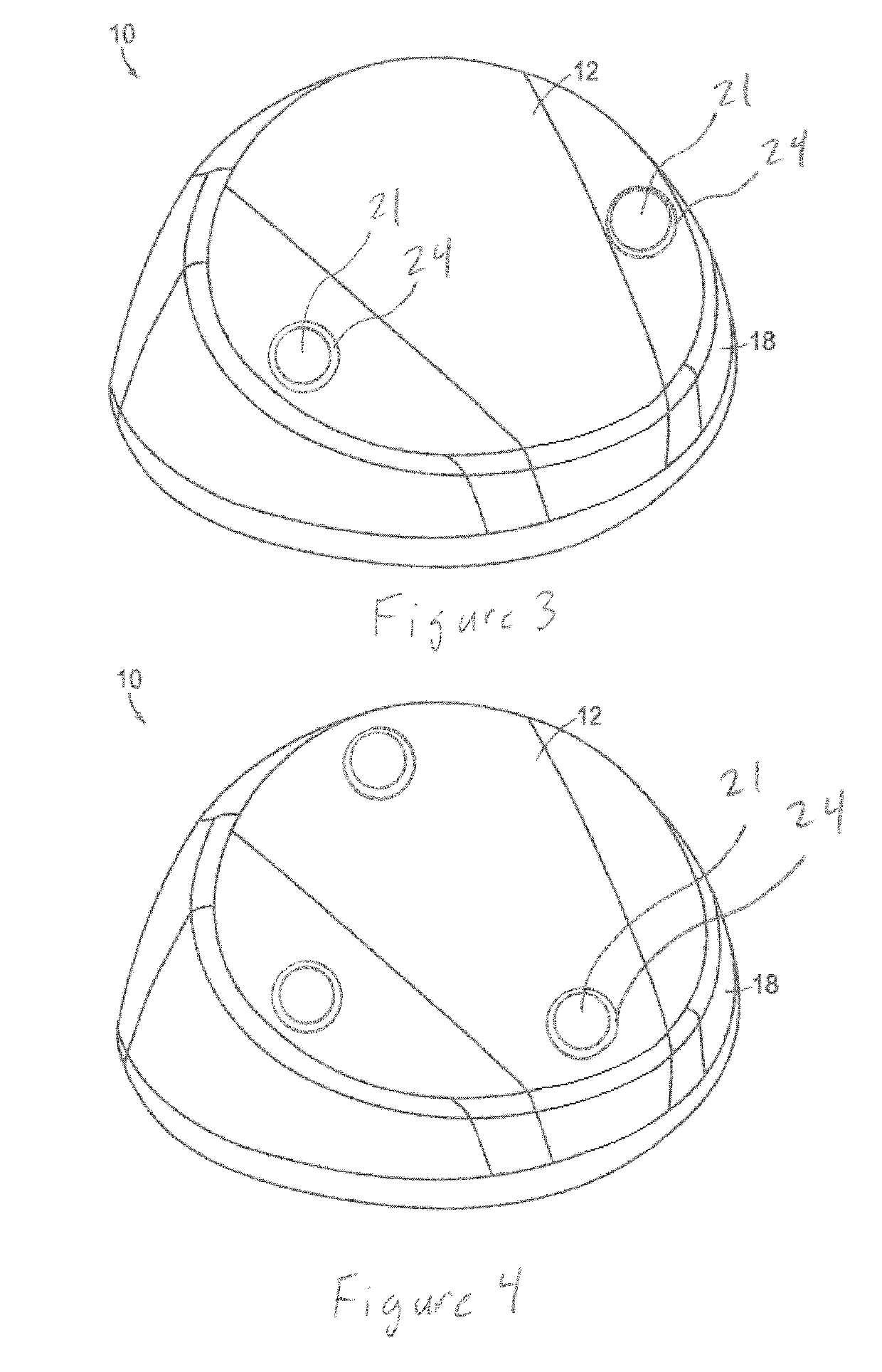
A golf club head having an exterior surface opposite the hollow golf club interior, the body having a center of gravity, wherein the body comprises an elongate weight receptacle, a weight retainer located in the weight receptacle, wherein the weight receptacle comprises a plurality of weight mounts, wherein the weight retainer is configured to slide along the weight receptacle between each of the plurality of weight mounts when the weight retainer is unlocked, and wherein the weight retainer is configured to reside in any of the plurality of weight mounts when the weight retainer is locked, and wherein the weight receptacle comprises a weight receptacle installation feature configured to receive the weight retainer, wherein the weight receptacle installation feature is located between two of the plurality of weight mounts, wherein the two of the plurality of weight mounts are located adjacent one another.

Description

RELATED APPLICATIONS[0001]The current application is a continuation of U.S. patent application Ser. No. 15 / 365,471, GOLF CLUB WITH MOVEABLE WEIGHT, to Cleghorn et al., filed Nov. 30, 2016, now U.S. Pat. No. 10,035,051, which is a continuation-in-part of U.S. patent application Ser. No. 15 / 282,854, GOLF CLUB WITH MOVABLE WEIGHT, to Frame et al., filed Sep. 30, 2016, now U.S. Pat. No. 9,975,019, which is a continuation-in-part of U.S. patent application Ser. No. 14 / 979,151, GOLF CLUB HAVING REMOVABLE WEIGHT, to Frame et al., filed on Dec. 22, 2015, now U.S. Pat. No. 9,744,415, as well as U.S. patent application Ser. No. 15 / 257,692, GOLF CLUB WITH MOVABLE WEIGHT, to Cleghorn et al., filed on Sep. 6, 2016, now U.S. Pat. No. 9,914,028, the disclosure of which are incorporated by reference in their entirety.TECHNICAL FIELD[0002]This present technology generally relates to systems, devices, and methods related to golf clubs, and more specifically to golf club heads having movable weights.D...

Claims


Application Information

Patent Timeline
Patent Type & Authority Patents(United States)
IPC IPC(8): A63B53/06A63B53/04A63B60/52A63B60/02
CPCA63B53/0433A63B53/0466A63B60/02A63B60/52A63B2053/0491A63B53/047A63B53/06
Inventor CLEGHORN, RICHARD L.FRAME, NICKGALVAN, DARRYL C.
Owner ACUSHNET CO
Learn More