Device and method for making a battery safe

a battery and safe technology, applied in the field of safety devices, can solve the problems of mechanical obstacle preventing an operator from using the safety device,

Active Publication Date: 2019-08-27
SAFT GRP SA
View PDF4 Cites 0 Cited by
  • Summary
  • Abstract
  • Description
  • Claims
  • Application Information

AI Technical Summary

Benefits of technology

[0012]The purpose of the present invention is to supply a device making it possible to resolve at least partially the aforementioned disadvantages.
[0013]More particularly, the invention aims to allow simple and rapid interconnection of a plurality of batteries, particularly of a set of batteries installed in the form of a bay, while still reducing the risks linked to an unsuitable interconnection of the batteries.
[0015]Such a safety device makes it possible to limit access to the positive and negative electrical terminals so that only the desired connection positions are accessible. The safety device therefore constitutes a mechanical obstacle preventing an operator from being mistaken about the desired connection position. This is particularly advantageous in a bay wherein a plurality of batteries are installed one above the others and interconnected in series in the same electrical circuit. In such a bay, the safety device makes it possible to avoid any risk of confusion by an operator charged with interconnecting the batteries by means of electrical connectors given that access to connection positions which can bring about a short-circuit is obstructed.
[0016]The safety device also makes it possible to reduce the assembly time of the electrical connectors on the batteries with respect to existing solutions, where only assembly schematics or assembly templates make it possible to correctly interconnect the batteries. In fact, only the connection positions wherein the electrical connectors are to be connected are accessible.
[0018]Moreover, the integration of the safety device at the battery module makes it possible not to force a user to use a specific type of electrical connector. In fact, any electrical connector adapted to be connected to the positive and negative terminals can be used.

Problems solved by technology

The safety device therefore constitutes a mechanical obstacle preventing an operator from being mistaken about the desired connection position.

Method used


Image

  • Device and method for making a battery safe
  • Device and method for making a battery safe
  • Device and method for making a battery safe

Examples


Embodiment Construction

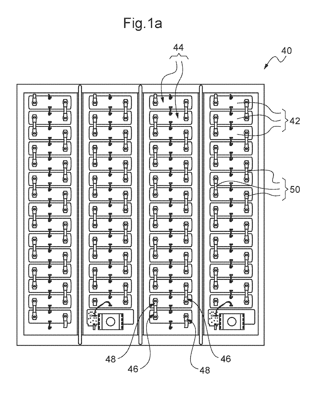
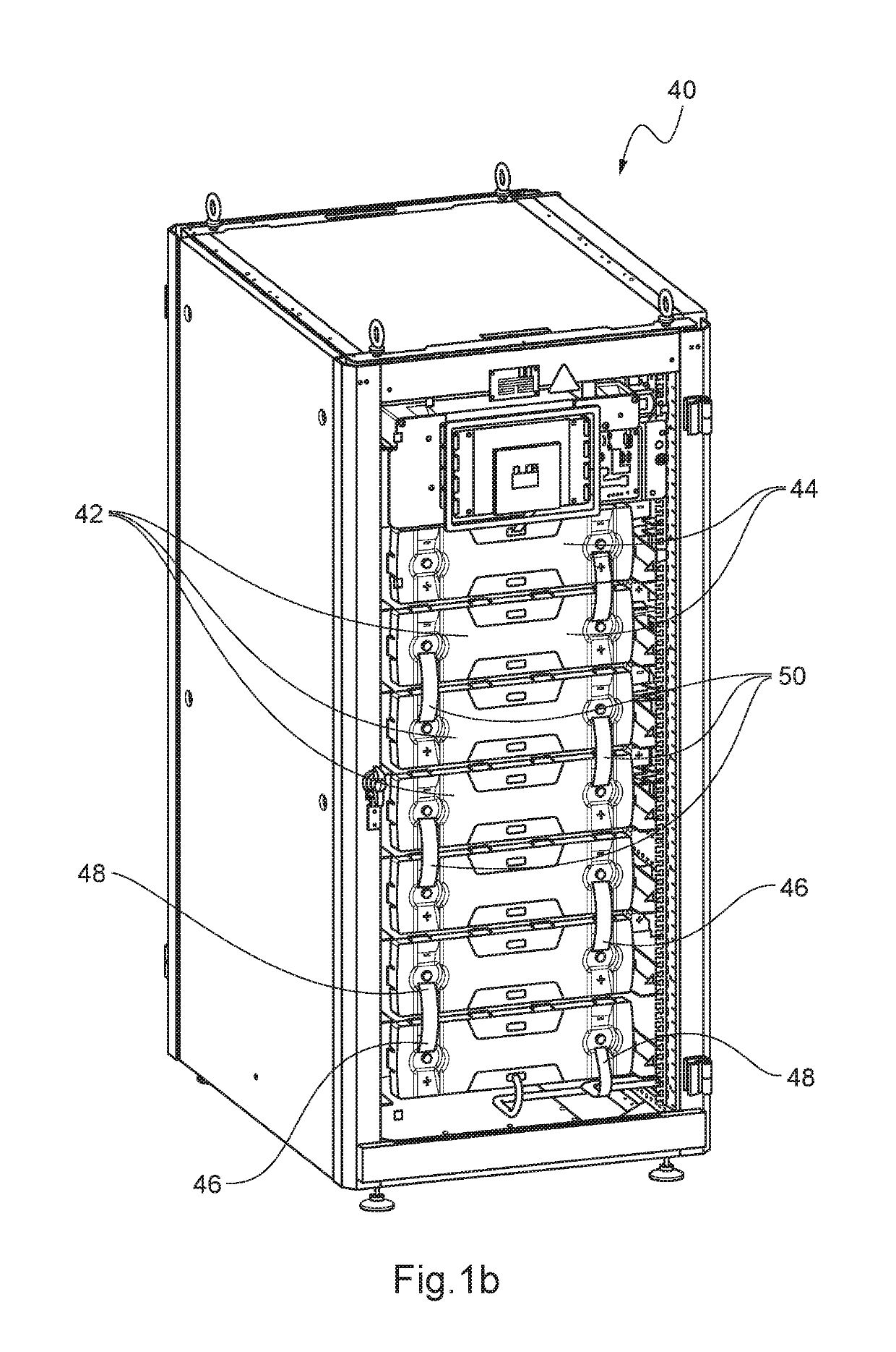
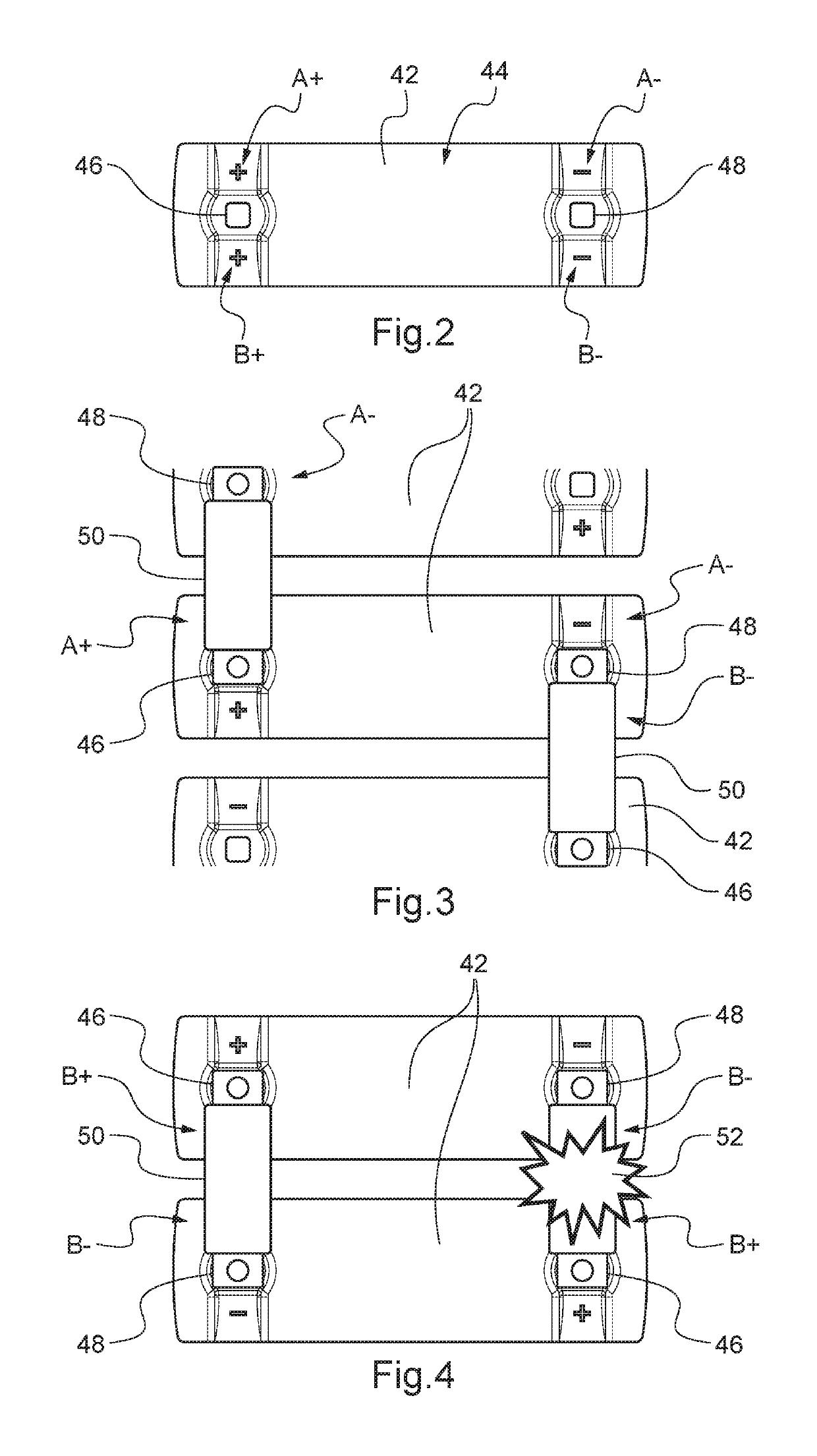
[0048]With reference to FIG. 5, a battery 12 is proposed intended to be used in a bay 40 shown in FIG. 1a, as a replacement for batteries 42. Moreover, the battery 12 is intended to be connected according to the connection assembly shown in FIG. 3, as a replacement for batteries 42.

[0049]The battery 12 comprises, at a connection wall 15, a positive electrical terminal 14 and a negative electrical terminal 16. Each of the positive 14 and negative 16 electrical terminals is adapted to be connected to an electrical connector 18 to connect the battery 12 to an electrical circuit or to another battery 12 comprised within the same electrical circuit.

[0050]To facilitate access to the positive 14 and negative 16 electrical terminals, the battery 12 is adapted so that the electrical connector 18 can be connected to each of the positive 14 and negative 16 electrical terminals using two connection positions. When the battery 12 is intended to be used in a bay 40 as shown in FIG. 1a, these two ...


PUM

PropertyMeasurementUnit
angleaaaaaaaaaa
electricalaaaaaaaaaa
electrical terminalsaaaaaaaaaa

Abstract

A safety device (19) for a battery (12) being designed so that an electrical connector (18) can be connected to the positive (14) and negative (16) electrical terminals of the battery (12) in a first (A+, A−) or a second (B+, B−) connection position, the safety device (19) being adapted to be selectively positioned in a first or a second safety position so that only the desired connection positions are accessible to an electrical connector (18). A battery including the safety device or a set of such batteries and a method for making such a set of batteries safe.

Description

BACKGROUND OF THE INVENTION[0001]Field of the Invention[0002]The present invention relates to a safety device for a battery or a set of batteries. The invention also relates to a battery suitable for being made safe by means of such a safety device, as well as a set of such batteries. The invention further relates to a method for making such a set of batteries safe.[0003]Prior Art[0004]Batteries are known which are designed based on electrochemical elements of the lithium-ion or nickel-metal hydride type designed to serve as emergency power supplies for low-voltage telecommunication networks. These batteries can be disposed in a modular casing, also called a bay or “rack.” Each bay can contain several batteries each delivering 48 V. A direct current to alternating current power converter (DC / AC) makes it possible to convert the direct current generated by the batteries into alternating current usable for supplying electronic systems of telecommunications networks. It is possible to ...

Claims


Application Information

Patent Timeline
Patent Type & Authority Patents(United States)
IPC IPC(8): H01M2/34H01R11/28H01M2/20H02J7/00H01R13/64H01M50/507H01M50/51H01M50/588
CPCH01R11/288H01R13/64H02J7/0045H01M2200/00H02J7/0029Y02E60/10H01M50/588H01M50/507H01M50/51H01M2220/10
Inventor NARBONNE, ALEXANDREDOS REIS, CHRISTOPHE
Owner SAFT GRP SA
Why Eureka
Try Eureka