Appliance for enteral nutrition

a technology for enteringal nutrition and gastrointestinal tract, applied in the field of enteral nutrition, can solve the problems of limiting the quality of patient monitoring, reducing the time needed for their use, and complicated fact for medical personnel, so as to reduce the time needed for their use. the effect of reducing the time needed for the use of the prob

Active Publication Date: 2019-09-03
STAMPI INDA DOLCIARIA AFFINI MILANO
View PDF8 Cites 0 Cited by
  • Summary
  • Abstract
  • Description
  • Claims
  • Application Information

AI Technical Summary

Benefits of technology

[0018]The main aim of the present invention is to provide an appliance that allows to simplify the use of the probes of known type by the medical staff.
[0019]Within this aim, one object of the present invention is to reduce significantly the time needed for their use.
[0020]Another object of the present invention is to reduce the health care costs related to the use of the probes of known type.
[0021]Another object of the present invention is to provide an appliance for enteral nutrition which allows to overcome the mentioned drawbacks of the prior art within the ambit of a simple, rational, easy, effective to use as well as low cost solution.

Problems solved by technology

In particular, the known probes allow the detection of the pressure at just one point along the tubular element, thus considerably limiting the quality of patient monitoring and, therefore, the possibility of appropriate interventions to regulate the assisted ventilation.
These in fact are complicated for medical personnel to use.
It follows that the use of the probes of known type proves to be considerably inconvenient from the point of view of the time required for their use and, therefore, also in economic terms, due to the exploitation of health personnel and medical hospital facilities.

Method used


Image

  • Appliance for enteral nutrition
  • Appliance for enteral nutrition

Examples


Embodiment Construction

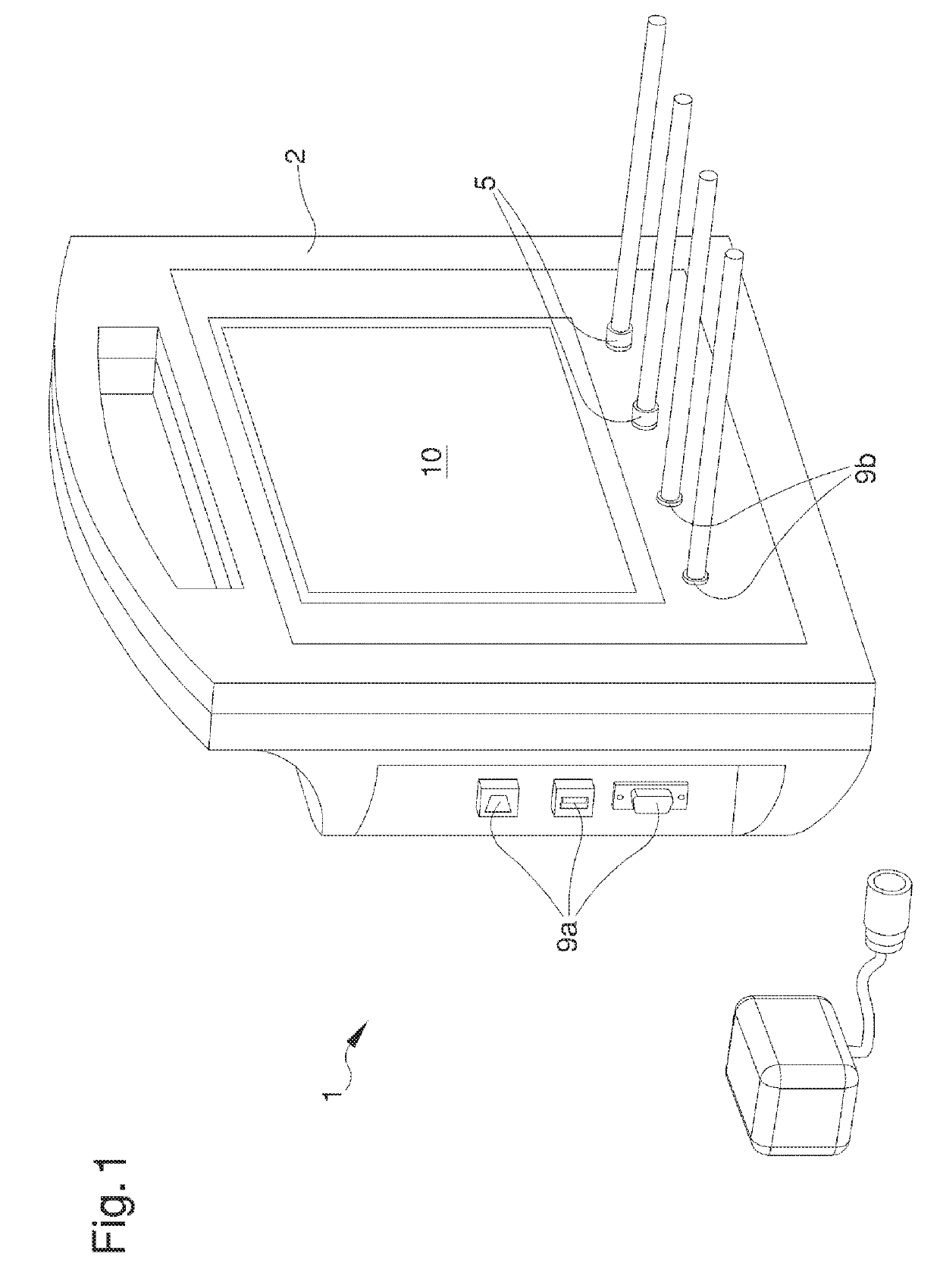
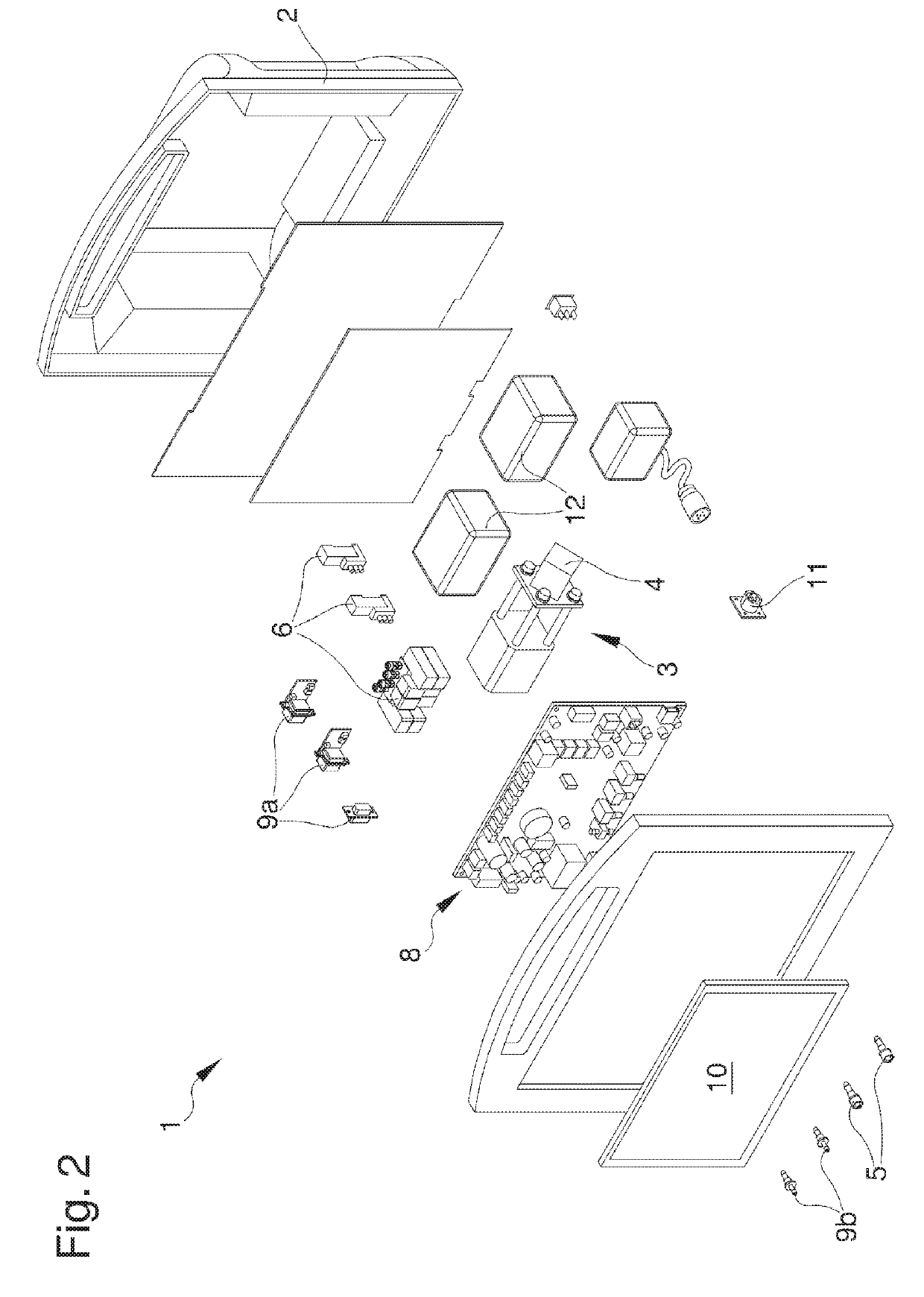
[0026]With particular reference to such figures, reference number 1 globally indicates an appliance for enteral nutrition by means of a probe of the type comprising a tubular element of elongated shape and substantially flexible which defines a feeding channel open at the extremities for the introduction of nutritional substances or drugs in the stomach of a patient or the aspiration of fluids from same.

[0027]The probes used, not shown in the enclosed illustrations, may be of two types.

[0028]The first type envisages the presence of a first inflatable balloon for detecting the pressure inside the patient's oesophagus, where the tubular element comprises at least a first air inlet / outlet mouth in / from the first balloon.

[0029]The second type envisages the presence of a first and a second inflatable balloon for detecting the patient's oesophageal and gastric pressure, where the tubular element comprises a first and a second air inlet / outlet mouth in / from the first and second balloon res...


PUM


Abstract

An appliance (1) for enteral nutrition by means of a probe of the type comprising a tubular element of elongated shape and substantially flexible which defines a feeding channel open at the extremities for the introduction of nutritional substances in the stomach of a patient and which comprises at least a first inflatable balloon for detecting the pressure inside the esophagus of a patient, the tubular element comprising at least a first inlet / outlet mouth for the air in / from the first balloon, the appliance (1) further comprising: at least a pneumatic circuit (3) having pumping means (4) associable at least with the first inlet / outlet mouth for inflating / deflating the first balloon; processing means (8) comprising: detection means which can be connected to the first balloon to detect the patient's oesophageal pressure (p.sub.es); reading means of the pressure of the respiratory tract (p.sub.aw) which can be connected to an external detection device; calculation means operatively connected to the detection means and to the reading means and able to calculate at least the transpulmonary pressure (p.sub.tp); graphic display means (10) operatively connected to the processing means (8) and able to display at least one of the oesophageal pressure (p.sub.es), the pressure of the respiratory tract (p.sub.aw) and the transpulmonary pressure (p.sub.tp).

Description

RELATED APPLICATIONS[0001]This application is a National Phase of PCT Patent Application No. PCT / IB2015 / 057169 having International filing date of Sep. 17, 2015, which claims the benefit of priority of Italian Patent Application No. MO2014A000273 filed on Sep. 23, 2014. The contents of the above applications are all incorporated by reference as if fully set forth herein in their entirety.FIELD AND BACKGROUND OF THE INVENTION[0002]The present invention relates to an appliance for enteral nutrition.[0003]In the medical field, so-called enteral nutrition is known of patients who must necessarily be fed artificially.[0004]In medical practice, to perform such nutrition gastric probes of different types are used, classified by location site and type of use.[0005]Nasogastric probes, e.g., are able to be introduced into a nostril of the nose, through the throat and the oesophagus, until they reach the patient's stomach.[0006]Known probes generally comprise a tubular element made of soft and...

Claims


Application Information

Patent Timeline
Patent Type & Authority Patents(United States)
IPC IPC(8): A61J15/00A61M16/04A61M16/00A61B5/08A61B5/03A61B5/00
CPCA61J15/0084A61J15/0076A61B5/037A61B5/08A61M16/044A61M16/026A61M16/0415A61J15/0073A61J15/0015A61J15/0049A61B5/6853A61B5/742A61J15/008A61B2560/0214A61M2205/3344A61M2205/505A61M2205/8206A61M2016/0027A61M2210/105
Inventor AZZOLINI, GRAZIANOMOJOLI, FRANCESCOTROMBA, ANDREA
Owner STAMPI INDA DOLCIARIA AFFINI MILANO
Why Eureka
Try Eureka