Fluid collection component comprising a film with fluid channels

a technology of fluid channel and collection component, which is applied in the direction of lighting and heating apparatus, process and machine control, instruments, etc., can solve the problems of poor long-term reliability, high cost, and complex electrical properties of many materials that change their optical properties

Active Publication Date: 2019-09-03
COLEMAN ZANE
View PDF8 Cites 10 Cited by
  • Summary
  • Abstract
  • Description
  • Claims
  • Application Information

AI Technical Summary

Benefits of technology

[0003]This invention generally relates to systems, devices, components and methods of their manufacture for transferring fluid from a first location to a second location. The system may comprise a film with film supporting members, such as without limitation, standoffs, or channels. In another embodiment, the system comprises a plurality of hollow fibers or tubes through which fluid flows. The fluid flow may, without limitation, transfer thermal energy or optically modifying materials. Examples include, without limitation, solar heat transfer films or fibers, color changing films or fibers, light transmission changing films or fibers, and optical property changing films or fibers. In one embodiment, a fluid transfer system comprises one or more fluid transfer components and one or more fluid input couplers or fluid output couplers. In a further embodiment, the fluid transfer system comprises one or more transfer fluids. In another embodiment, the fluid transfer system comprises a flow source for moving the fluid in the system. In one embodiment, the fluid transfer system delivers fluid to an active region, receives fluid from an active region, or passes a fluid through an active region. In one embodiment, a first fluid in the active region (or in one or more channels within the active region) of the fluid transfer flows out of the active region and a second fluid different from the first fluid flows into the active region. In another embodiment, the fluid receives or delivers energy, such as thermal energy, in the active region and delivers or receives, respectively, the energy to a second component in the fluid transfer system, such as a heat exchanger. In one embodiment, the active region of the fluid transfer system changes from a first optical state to a second optical state due to fluid transition within one or more channels in a film. In another embodiment, the fluid transfer component comprises at least one liquid input coupler or liquid output coupler. In another embodiment, the liquid input coupler and / or the liquid output coupler comprises a fluid channel geometry converter. In one embodiment, the fluid transfer system comprises a film with one or more layers, wherein a fluid input coupler, an active region, and a fluid output coupler comprise regions of the film. In another embodiment, the fluid transfer component comprises film-based fluid channels converted from a first spatial arrangement geometry to a second spatial arrangement geometry different from the first spatial arrangement geometry. In another embodiment, the fluid transfer component comprises at least one of a fluid input coupler and fluid output coupler comprising a fluid channel geometry converter comprising re-arranged extended segments of a film comprising the active region fluid channels. As used herein a fluid transfer component may control and / or manipulate the flow or transfer of any type of fluid and may comprise channels, chambers and other fluidic component that behave as do most macroscopic systems, or the devices or components can be constructed in a way so that they are considered microfluidic devices.

Problems solved by technology

Many materials that change their optical properties are typically electrically complex, expensive and have poor long term reliability.

Method used


Image

  • Fluid collection component comprising a film with fluid channels
  • Fluid collection component comprising a film with fluid channels
  • Fluid collection component comprising a film with fluid channels

Examples


Embodiment Construction

[0026]The features and other details of the invention will now be more particularly described. It will be understood that particular embodiments described herein are shown by way of illustration and not as limitations of the invention. The principal features of this invention can be employed in various embodiments without departing from the scope of the invention. All parts and percentages are by weight unless otherwise specified.

Glossary

[0027]In describing one or more embodiments, the following terms are defined as set forth below:

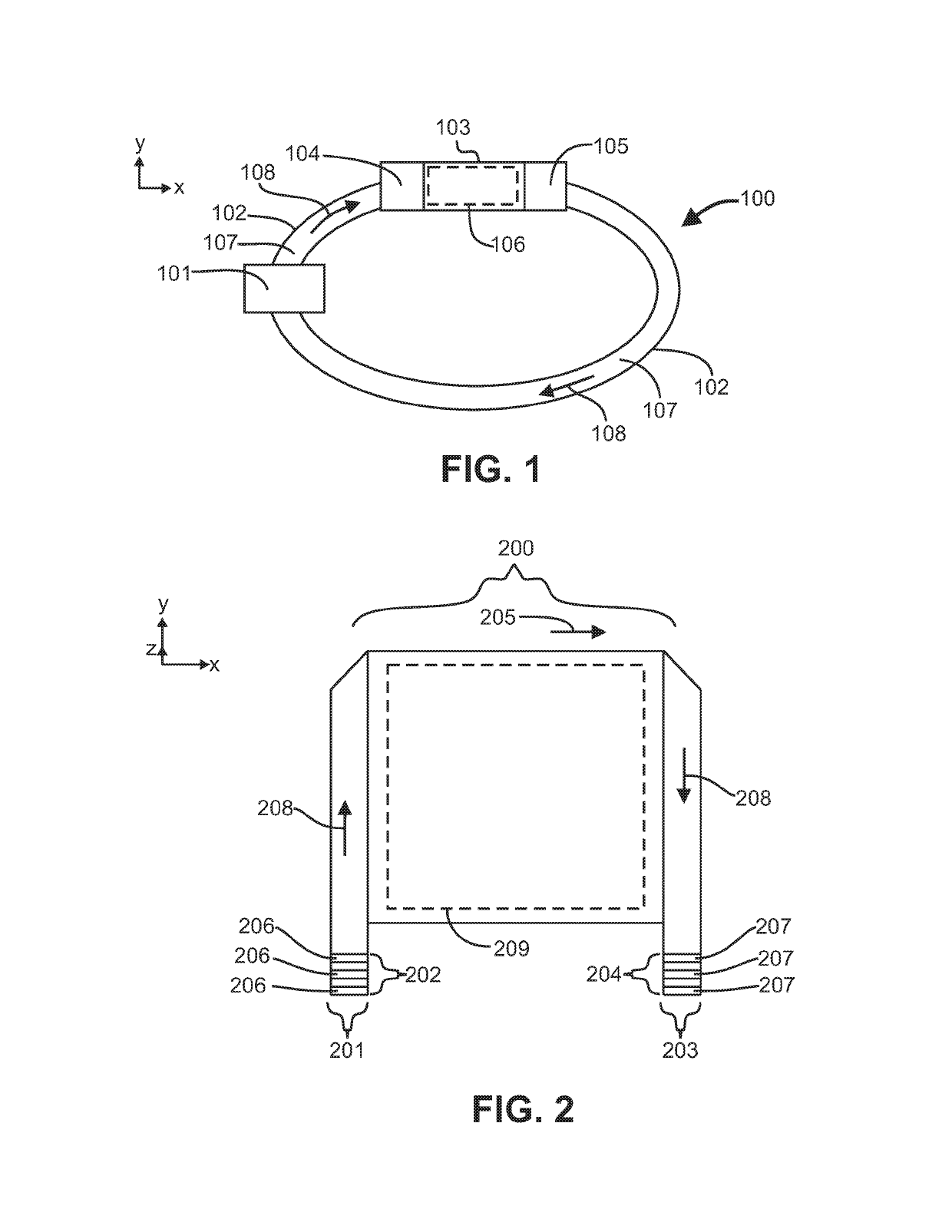
[0028]“Channel” as used herein is to be interpreted in a broad sense. Thus, it is not intended to be restricted to elongated configurations where the transverse or longitudinal dimension greatly exceeds the diameter or cross-sectional dimension. Rather, such terms are meant to comprise cavities or tunnels of any desired shape or configuration through which fluids may be directed. Such a fluid cavity may, for example, comprise a flow-through cell where flu...


PUM


Abstract

In one embodiment, a device comprises a fluid transfer component having an average thickness less than 2 millimeters and comprising a polymer film with one or more polymeric materials in one or more layers; and an active region of the fluid transfer component comprising a surface area greater than 1 square meter and plurality of fluid channels defined by one or more interior surfaces within the polymeric film, each fluid channel of the plurality of fluid channels is separated spatially with the plurality of fluid channels comprising at least 1 row of fluid channels in a thickness direction of the polymeric film, wherein the plurality of fluid channels has a channel density across the active region of the fluid transfer component greater than 100 fluid channels per centimeter and the plurality of fluid channels collects a first fluid across the active region from the environment.

Description

CROSS-REFERENCE TO RELATED APPLICATIONS[0001]This application is a continuation-in-part of U.S. application Ser. No. 13 / 680,010 filed Nov. 16, 2012, entitled “Fluid transfer systems, devices, components, and methods of manufacture,” which claims the benefit of U.S. Provisional Application No. 61 / 560,295 entitled “Fluid transfer system, devices, components, and method of manufacture” filed Nov. 16, 2011, the entire contents of each are incorporated by reference herein.BACKGROUND[0002]Many materials that change their optical properties are typically electrically complex, expensive and have poor long term reliability. Fluid transfer systems are needed that are simple, do not leak or having complex or unreliable coupling to fluid transfer components, or have a high flow resistance.BRIEF SUMMARY[0003]This invention generally relates to systems, devices, components and methods of their manufacture for transferring fluid from a first location to a second location. The system may comprise a...

Claims


Application Information

Patent Timeline
Patent Type & Authority Patents(United States)
IPC IPC(8): F28F7/00G05D7/00
CPCG05D7/00
Inventor COLEMAN, ZANE
Owner COLEMAN ZANE
Why Eureka
Try Eureka