Control system for controlling operation of a machine by imposing shaped hysterisis

a control system and machine technology, applied in the field of control systems, can solve problems such as undesirable steady state error in response, filter performance sluggishness, and sensitive signals received from sensors

Active Publication Date: 2019-09-03
CATERPILLAR INC
View PDF9 Cites 0 Cited by
  • Summary
  • Abstract
  • Description
  • Claims
  • Application Information

AI Technical Summary

Problems solved by technology

The signals received from the sensors are susceptible to noise, and therefore filtering of the signals is carried out.
However, sometimes the filters provide sluggish performance due to their inherent behavior.
The hysteresis techniques may cause an undesirable steady state error in response when an operator provides an input to any of the control element for controlling operations of the machine.
The undesirable steady state error in response in controlling operation of the machine is not a desirable characteristic of the machine when the input provided by the operator is at or near zero and at or near a maximum input range of the input device.

Method used


Image

  • Control system for controlling operation of a machine by imposing shaped hysterisis
  • Control system for controlling operation of a machine by imposing shaped hysterisis
  • Control system for controlling operation of a machine by imposing shaped hysterisis

Examples


Embodiment Construction

[0013]Reference will now be made in detail to specific embodiments or features, examples of which are illustrated in the accompanying drawings. Wherever possible, corresponding or similar reference numbers will be used throughout the drawings to refer to the same or corresponding parts.

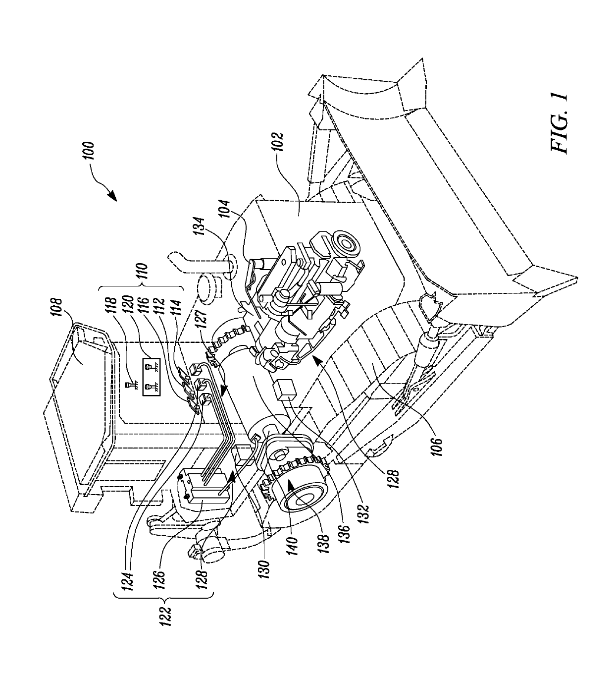
[0014]FIG. 1 is an illustration of an exemplary machine 100, according to one embodiment of the present disclosure. The machine 100 may be a mobile machine that performs some type of operation associated with an industry such as mining, construction, farming, transportation, or another industry known in the art. As illustrated, the machine 100 may embody a track type tractor. However, it may be contemplated that the machine 100 may be an earth-moving machine such as a track-type dozer, loader, excavator, agricultural tractor, or haul machine.

[0015]As illustrated in FIG. 1, the machine 100 may include, but not limited to, a frame 102, and an engine 104 mounted to the frame 102 of the machine 100. The e...


PUM


Abstract

A control system for a machine having at least one control element is disclosed. The control system includes multiple input sensors in communication with the control element. The input sensor generates an input signal based on an input to the control element. The control system includes multiple actuating members to control operations of the machine. The control system includes a controller in communication with the input sensors and the actuating members. The controller receives the input signal from the input sensor and determines an imposed hysteresis level corresponding to the input signal based on a hysteresis input function. The controller is further configured to generate a hysteresis conditioned input signal based on the imposed hysteresis level.

Description

TECHNICAL FIELD[0001]The present disclosure relates generally to control systems and, more particularly, relates to a control system for controlling operations of a machine having at least one control element.BACKGROUND[0002]Machines include a number of control elements such as brake pedal, accelerator pedal, clutch pedal, gear and the steering system that are adapted to receive operator inputs pertaining to an intended operation of the machine. The control elements give control signals to a controller for accordingly controlling operations of the machine. Typically, the control elements are connected to sensors. The sensors generate signals based on the operator input to the control element and communicate the control signals to the controller. The signals received from the sensors are susceptible to noise, and therefore filtering of the signals is carried out. The controller implements conventional filters for mitigating the noise in the signals received from the sensors. However,...

Claims


Application Information

Patent Timeline
Patent Type & Authority Patents(United States)
IPC IPC(8): H03K3/037
CPCH03K3/0377
Inventor KURAS, BRIAN D.BARNGROVER, MICHAEL J.SONTH, SANGAMESHWAR
Owner CATERPILLAR INC
Why Eureka
Try Eureka