Mobile communications system, methods, controller, relay node and communications terminal

a mobile communication system and relay node technology, applied in wireless communication, wireless communication, transmission path division, etc., can solve the problems of relay nodes consuming too much power, poor connection of communication terminals, increasing latency and delays, etc., to reduce traffic or power load, increase latency and delays, and reduce power consumption

Active Publication Date: 2019-09-03
SONY CORP
View PDF9 Cites 2 Cited by
  • Summary
  • Abstract
  • Description
  • Claims
  • Application Information

AI Technical Summary

Benefits of technology

[0010]When a communications terminal communicates via a relay node to an eNodeB, there are several potential issues. The first of these is that the communications terminal may have a poor connection to that relay node, or the relay node may be consuming too much power or dealing with too much traffic. The relay node is likely to be capacity limited, and if the amount of traffic being communicated between the communications terminal and the eNodeB via the relay node is greater than the relay node's capacity, it may become a bottleneck to the system, thereby increasing latency and delays, as well as wasting power and causing the mobile communications system to be more inefficient in general. The provision of a second relay node in order to alleviate the traffic or power load on a capacity constrained relay node, or a relay node which is communicating with a communications device via an instable or low quality channel, may provide a solution to some or all of these issues.
[0011]Embodiments of the present disclosure, then, can increase a communications bandwidth available to a communications terminal, for example where a relatively high amount of data needs to be communicated by a communications terminal to an eNodeB, or where the communications terminal may be out of coverage of the eNodeB. This may be achieved through the employment of a dual connection, with two relay nodes relaying signals between the communications terminal and the eNodeB. This in itself has its own challenges to overcome, and the present disclosure also reduces a likelihood or avoids a conflict in communications between the communications terminal and a relay node when more than one relay node is used.
[0013]Further, the traffic load of a relay node operating alone between a communications terminal and a base station may be greater than its capacity, thereby causing the relay node to become a bottleneck to the mobile communications system. In this case, latency would be increased and the mobile communications system would suffer delays, which would be problematic in time-critical scenarios such as video streaming etc. In order to reduce this latency, a second relay node could be activated to provide a dual connection implementation where the traffic load of a single relay node is alleviated.

Problems solved by technology

When a communications terminal communicates via a relay node to an eNodeB, there are several potential issues.
The first of these is that the communications terminal may have a poor connection to that relay node, or the relay node may be consuming too much power or dealing with too much traffic.
The relay node is likely to be capacity limited, and if the amount of traffic being communicated between the communications terminal and the eNodeB via the relay node is greater than the relay node's capacity, it may become a bottleneck to the system, thereby increasing latency and delays, as well as wasting power and causing the mobile communications system to be more inefficient in general.
Further, an out-of-coverage communications terminal may not be able to communicate directly with the base station, and therefore relies on an associated relay node to relay communications.
Should the radio communications channel between the communications terminal and the relay node be of a low quality or stability, communications will become severely affected.

Method used


Image

  • Mobile communications system, methods, controller, relay node and communications terminal
  • Mobile communications system, methods, controller, relay node and communications terminal
  • Mobile communications system, methods, controller, relay node and communications terminal

Examples


Embodiment Construction

[0028]Hereinafter preferred embodiments of the present technique will be described in detail with reference to the appended drawings. Note that, in this specification and appended drawings, structural elements that have substantially the same function and structure are denoted with the same reference numerals, and repeated explanation of these structural elements is omitted.

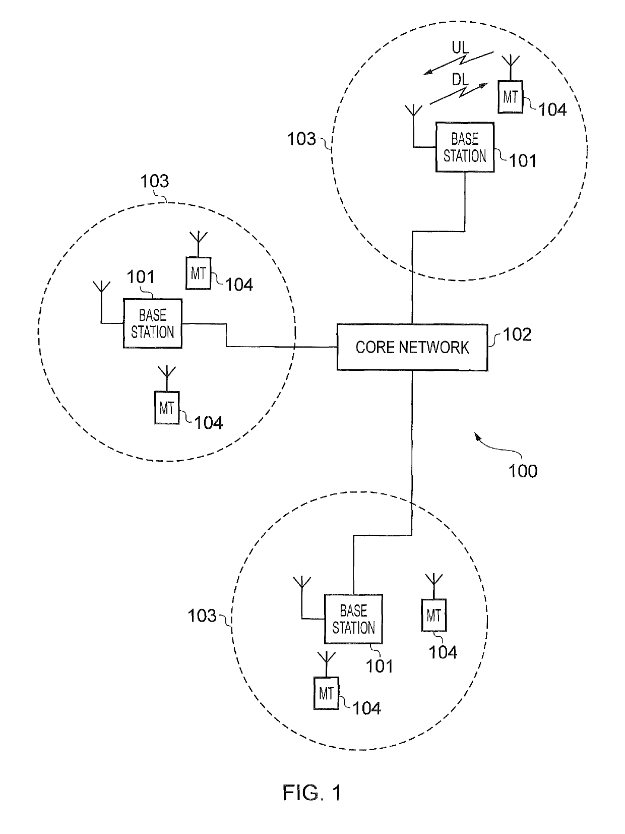
[0029]FIG. 1 provides a schematic diagram illustrating some basic functionality of a conventional mobile telecommunications network, using for example a 3GPP defined UMTS and / or Long Term Evolution (LTE) architecture. The mobile telecommunications network / system 100 of FIG. 1 operates in accordance with LTE principles and which may be adapted to implement embodiments of the disclosure as described further below. Various elements of FIG. 1 and their respective modes of operation are well-known and defined in the relevant standards administered by the 3GPP (RTM) body, and also described in many books on the subject...


PUM


Abstract

A controller is configured to control a first of plural relay nodes to transmit signals representing data to one of communications terminals received from a base station or to receive signals representing data from a communications terminal for transmission to the base station, wherein, upon first predetermined conditions being met, to control a second of the plurality of relay nodes to transmit signals representing the data to the communications terminal received from the base station or to receive signals representing the data from the communications terminal for transmission to the base station, and to control the communications terminal to transmit a first signal representing at least a first part of the data to the first relay node for transmission to the base station, and to transmit a second signal representing at least a second part of the data to the second relay node for transmission to the base station.

Description

CROSS-REFERENCE TO RELATED APPLICATIONS[0001]The present application is based on PCT filing PCT / EP2016 / 058897 filed Apr. 21, 2016, and claims priority to European Patent Application 15 167 227.6, filed in the European Patent Office on May 11, 2015, the entire contents of each of which being incorporated herein by reference.TECHNICAL FIELD OF THE DISCLOSURE[0002]The present disclosure relates to mobile communications networks, methods, relay nodes and communications terminals, and more specifically to providing an arrangement in which a communications terminal communicates with a base station via a relay node.[0003]Embodiments of the present technique can provide methods of communicating data in a small cell environment where relay nodes may be used.BACKGROUND OF THE DISCLOSURE[0004]The “background” description provided herein is for the purpose of generally presenting the context of the disclosure. Work of the presently named inventors, to the extent it is described in this backgrou...

Claims


Application Information

Patent Timeline
Patent Type & Authority Patents(United States)
IPC IPC(8): H04W4/00H04B7/155H04W76/15H04W40/04H04W40/12H04W40/22H04W40/34H04B7/26H04L5/00
CPCH04W40/04H04W40/12H04W40/22H04W76/15H04B7/15528H04B7/2606H04W40/34H04L5/001
Inventor WAKABAYASHI, HIDEJIMARTIN, BRIAN ALEXANDERTSUDA, SHINICHIRO
Owner SONY CORP
Why Eureka
Try Eureka