
Slide out pump stand for hydraulic fracturing equipment

a hydraulic fracturing and pump stand technology, applied in machines/engines, positive displacement liquid engines, transportation items, etc., can solve the problems of high risk of height, eroded seats and valves, and eroded replacement parts, so as to prevent damage to at least one electric devi

Active Publication Date: 2019-09-10
US WELL SERVICS LLC
View PDF293 Cites 161 Cited by
  • Summary
  • Abstract
  • Description
  • Claims
  • Application Information

AI Technical Summary

Benefits of technology

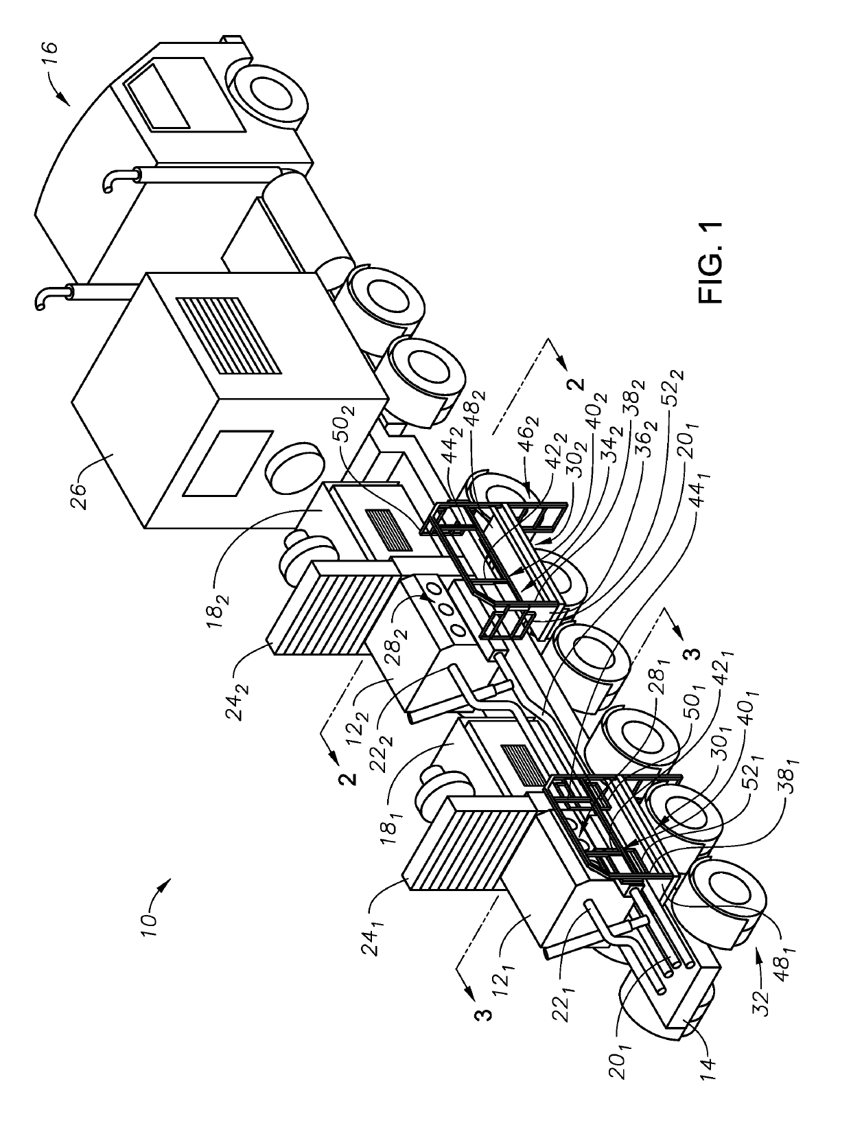
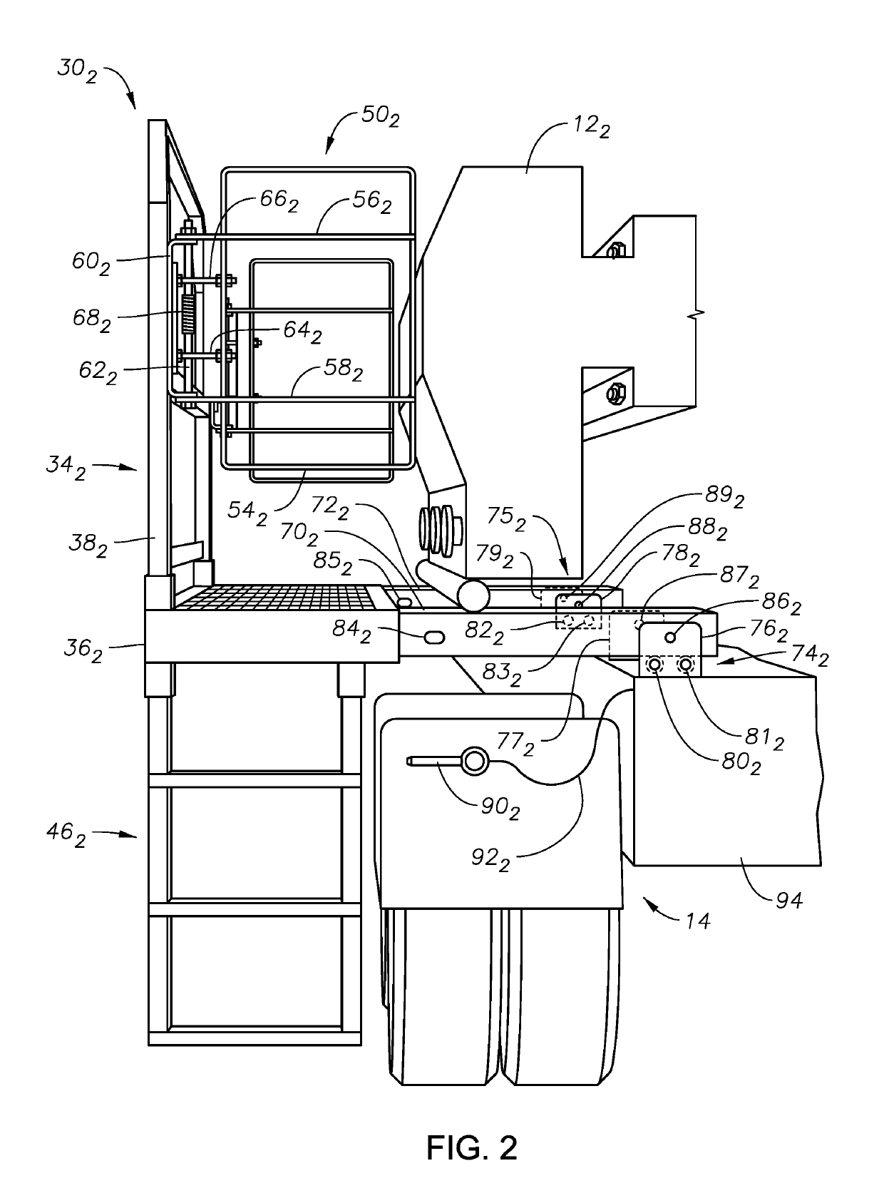
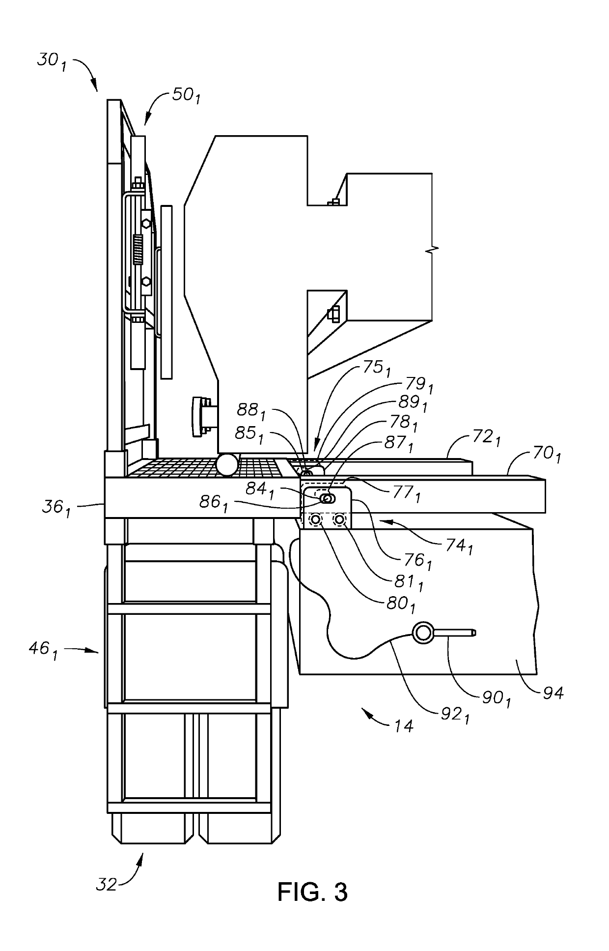
The patent describes a hydraulic fracturing system for fracturing underground formations. The system includes a trailer, a pump, an electric motor, and a platform assembly. The platform assembly is connected to the trailer and includes a lateral rail assembly, end gates, and elastomeric bungees. The platform assembly can be moved between a stowed configuration and a deployed configuration. The system also includes a variable frequency drive to control the speed of the motor and a diagnostics tool to prevent motor damage. The technical effects of the patent include improved safety and efficiency in hydraulic fracturing operations.

Problems solved by technology

These seats and valves often erode due to the proppant in the fracturing fluid; which sometimes requires frequent replacement.
Replacing the eroded components can be hazardous as the fluid ends are typically above grade on mobile trailers, and which generally have limited space on which maintenance personnel can stand.
The height hazard is compounded by the use of heavy pump tools for assembly and disassembly of the fluid end for part replacement.

Method used


Image

  • Slide out pump stand for hydraulic fracturing equipment
  • Slide out pump stand for hydraulic fracturing equipment
  • Slide out pump stand for hydraulic fracturing equipment

Examples


Embodiment Construction

[0016]The method and system of the present disclosure will now be described more fully hereinafter with reference to the accompanying drawings in which embodiments are shown. The method and system of the present disclosure may be in many different forms and should not be construed as limited to the illustrated embodiments set forth herein; rather, these embodiments are provided so that this disclosure will be thorough and complete, and will fully convey its scope to those skilled in the art. Like numbers refer to like elements throughout. In an embodiment, usage of the term “about” includes + / −5% of the cited magnitude. In an embodiment, usage of the term “substantially” includes + / −5% of the cited magnitude.

[0017]It is to be further understood that the scope of the present disclosure is not limited to the exact details of construction, operation, exact materials, or embodiments shown and described, as modifications and equivalents will be apparent to one skilled in the art. In the ...


PUM


Abstract

A hydraulic fracturing system has a pump driven by an electrically powered motor. The pump pressurizes fluid which is piped into a wellbore to fracture a subterranean formation. The pump and motor are mounted on a trailer that is hitched to a tractor. A platform assembly is mounted onto the trailer, and which is selectively moveable between deployed and stowed configurations. The platform assembly includes a platform, a lateral rail assembly mounted to the platform, and gates on the forward and aft ends of the platform. The rail assembly and gates define a safety barrier to prevent operations personnel from falling off the platform. In the stowed configuration the platform assembly is anchored in place over wheels on the trailer. In the deployed configuration, the platform assembly provides work surface so that operations personnel can readily access the pump on the trailer.

Description

CROSS REFERENCE TO RELATED APPLICATIONS[0001]This application claims priority to and the benefit of, U.S. Provisional Application Ser. No. 62 / 196,525, filed Jul. 24, 2015, and is a continuation-in-part of, and claims priority to and the benefit of co-pending U.S. patent application Ser. No. 13 / 679,689, filed Nov. 16, 2012, the full disclosures of which are hereby incorporated by reference herein for all purposes.BACKGROUND OF THE INVENTION[0002]1. Field of Invention[0003]The present disclosure relates to a system for hydraulically fracturing a subterranean formation. More specifically, the present disclosure relates to a frame for hydraulic fracturing equipment that includes a retractable platform.[0004]2. Description of Prior Art[0005]Hydraulic fracturing is a technique used to stimulate production from some hydrocarbon producing wells. The technique usually involves injecting fluid into a wellbore at a pressure sufficient to generate fissures in the formation surrounding the wellb...

Claims


Application Information

Patent Timeline
Patent Type & Authority Patents(United States)
IPC IPC(8): E21B7/02F04B49/06B60P7/08B60P3/00F04B17/03F04B47/02
CPCE21B7/02E21B7/022E21B7/026F04B49/06B60P7/0815F04B17/03F04B47/02B60P3/00
Inventor OEHRING, JAREDHINDERLITER, BRANDON NEIL
Owner US WELL SERVICS LLC
Learn More