Skin treatment device for multi-photon based skin treatment

a skin treatment and photon based technology, applied in the field of skin treatment using laser light, can solve the problem of challenging to achieve multi-photon ionization deep inside the skin

Active Publication Date: 2019-09-17
KONINKLJIJKE PHILIPS NV
View PDF11 Cites 0 Cited by
  • Summary
  • Abstract
  • Description
  • Claims
  • Application Information

AI Technical Summary

Benefits of technology

[0012]The invention is based on the insight that the intensity threshold to create multi-photon ionization is a function of both medium characteristics and beam characteristics. The medium characteristics may, for example, be ionization energy or impurity levels, and the beam characteristics may, for example, be wavelength used, pulse width, spot size, and polarization. To generate a seed electron for the multi-photon ionization process, multiple photons having the same polarization direction are necessary at the target position. When polarized light is focused inside turbid media like skin, the fraction of photons having the same polarization is significantly reduced. This is caused by the change in polarization due to high NA focusing, multiple scattering and skin birefringence. To compensate for the reduction in the number of photons with the same polarization available for multi-photon ionization in the focal volume, the known solution is to increase simply the number of photons. In the known skin treatment devices, this leads to a high intensity threshold for ionization and possible collateral damage of the surrounding tissue. The inventors have found that for a specific polarization direction also indicated as the optimum polarization direction the depolarization effect of the skin at a specific skin position is at a minimum. This results in a minimum power level of the treatment light required to generate multi-photon ionization. The inventors have also found that this optimum polarization direction may differ at different locations in the skin tissue. Therefore, the skin treatment device according to the invention comprises a polarization modulator which is controlled by a control unit to locally adapt the polarization direction of the emitted linearly polarized probe light to find the optimum polarization direction. Subsequently initiating the emission of treatment light with a polarization direction corresponding to this optimum polarization direction for the current target position will result in the generation of the multi-photon ionization process at a minimum treatment light intensity. As a result, damage to the tissue surrounding the target position is minimized. A further benefit of this local selection and adaption of the polarization direction of the linearly polarized probe light (and treatment light) by the polarization modulator is that it may also reduce the requirements imposed on the light source for generating the polarized treatment light. This would subsequently also reduce the overall cost of the skin treatment device according to the invention.
[0021]In an embodiment of the skin treatment device, a probe light power level is below a treatment light power level required for the multi-photon process. When using probe light which has a lower power level than the treatment light to find the optimum polarization direction, the chances of damaging the skin while trying to find the optimum polarization direction are significantly reduced. Still, using this probe light having the lower power level allows selecting the optimum polarization direction of the current target position. Furthermore, the power requirements of such a probe light are significantly lower than the power required to generate the multi-photon ionization process. Consequently, by using probe light when scanning the polarization modulator to find the minimum depolarization, the overall power requirements of the skin treatment device are reduced. Especially in an embodiment in which the skin treatment device may be battery-operated, such a reduction in overall power requirements may be important.
[0022]In an embodiment of the skin treatment device, the light source comprises a probe light emitter for generating the linearly polarized probe light, and comprises a treatment light emitter for generating the linearly polarized treatment light. A benefit of such an embodiment is that both the probe light emitter and the treatment light emitter may each be specifically configured to emit their individually required power levels, which may reduce the overall requirements of the individual light emitters. Furthermore, a power level adjustment circuit, which could be required when only a single light emitter were present, may be omitted.

Problems solved by technology

Multi-photon ionization deep inside skin is challenging to achieve.

Method used


Image

  • Skin treatment device for multi-photon based skin treatment
  • Skin treatment device for multi-photon based skin treatment
  • Skin treatment device for multi-photon based skin treatment

Examples


first embodiment

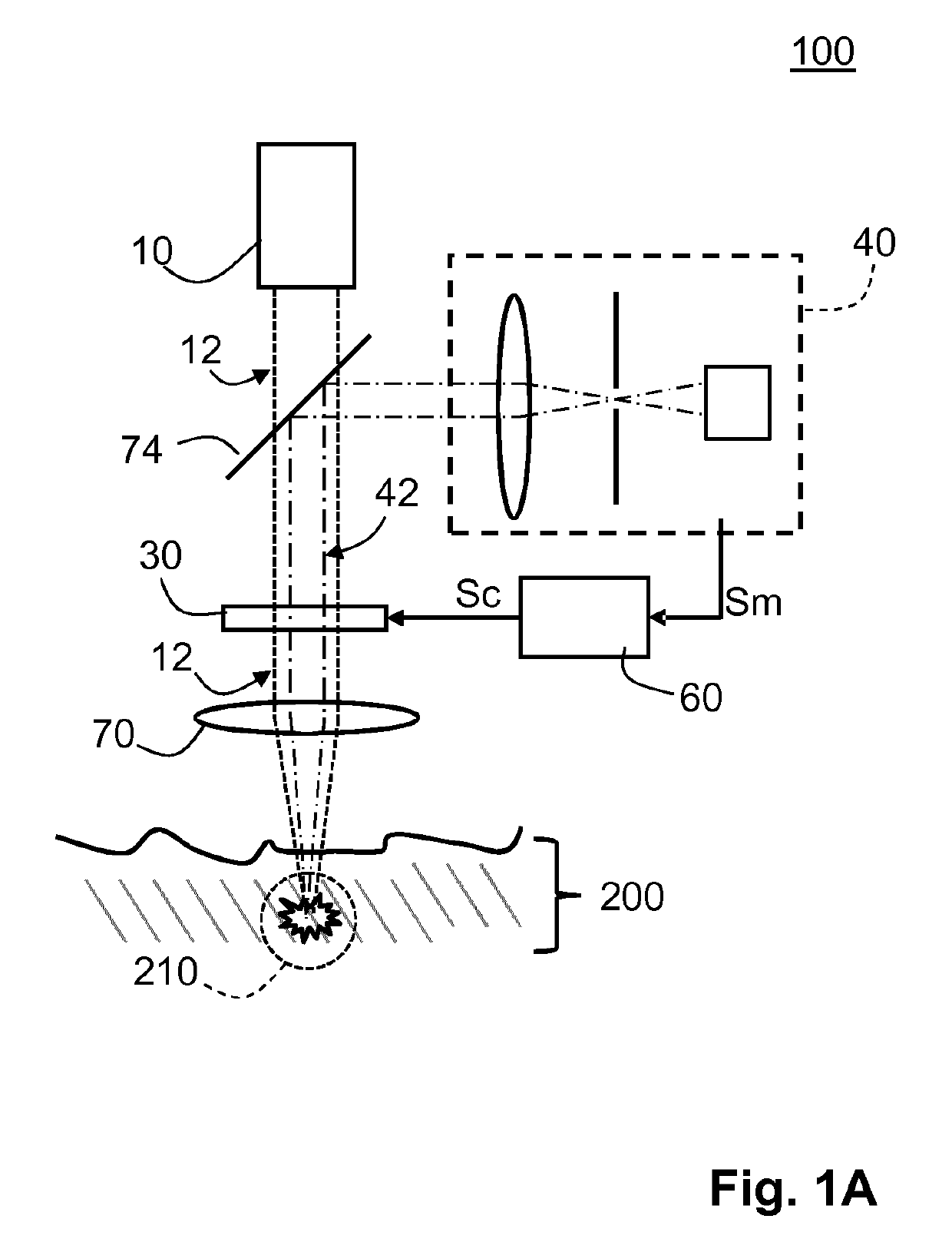
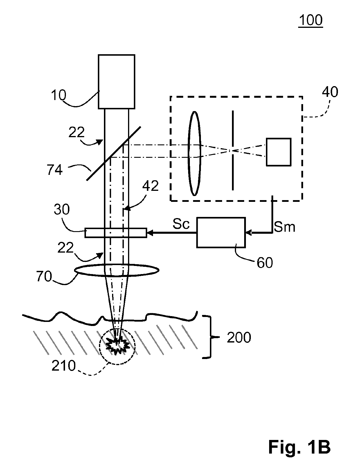
[0039]FIGS. 1A and 1B diagrammatically show the skin treatment device 100 according to the invention. The skin treatment device 100 comprises a light source 10 constructed and configured for generating linearly polarized probe light 12 and linearly polarized treatment light 22 (see FIG. 1B). The skin treatment device 100 further comprises a polarization modulator 30 for controlling a polarization direction of the linearly polarized probe light 12 received from the light source 10, which light is emitted and focused using an optical system 70 toward the target position 210 inside the skin tissue 200. The skin treatment device 100 also comprises a polarization sensitive sensor 40 for sensing an intensity of the back-scattered probe light 42 from the target position 210. The polarization sensitive sensor 40 is configured for sensing a level of depolarization of the probe light 12 by sensing an intensity of back-scattered probe light 42 from the target position 210 in a predefined polar...

second embodiment

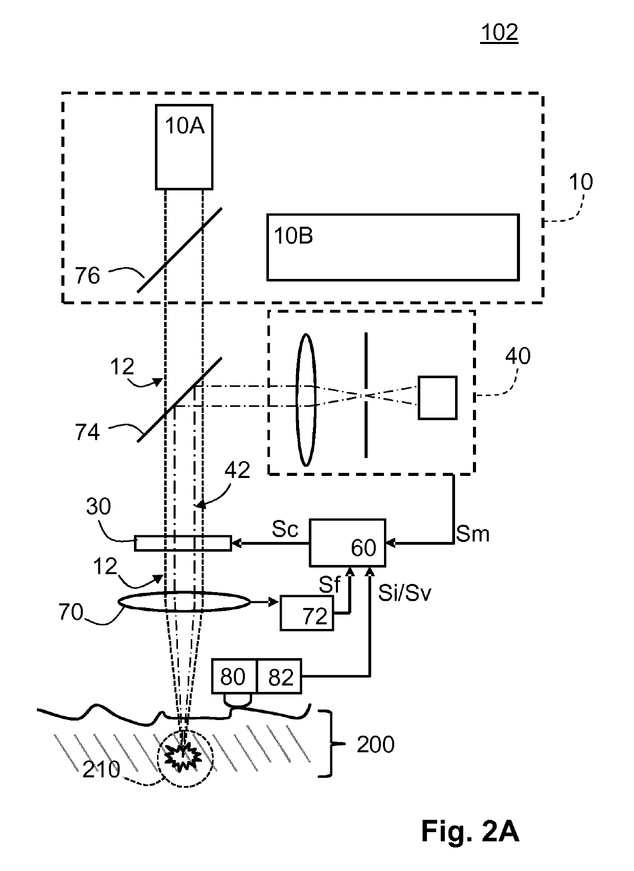
[0061]FIGS. 2A and 2B diagrammatically show the skin treatment device 102 according to the invention. In the embodiment shown in FIGS. 2A and 2B, the polarization modulator 30, the sensor 40, the controller 60 and the optical system 70 are identical to the embodiment shown in FIGS. 1A and 1B. However, in the embodiment shown in FIGS. 2A and 2B, the skin treatment device 102 comprises a light source 10 having a probe light emitter 10A and a separate treatment light emitter 10B. The probe light emitter 10A is configured for generating probe light 12 being linearly polarized light having an intensity level significantly below the intensity level required for generating the multi-photon ionization. The treatment light emitter 10B is configured for generating treatment light 22 being linearly polarized light having an intensity at or above the intensity level required for the multi-photon ionization process. As indicated before, the use of separate light emitters for, on the one hand, th...


PUM


Abstract

The invention provides a non-invasive skin treatment device (100) comprising: a light source (10) constructed and configured for generating linearly polarized probe light (12) and linearly polarized treatment light (22), a polarization modulator (30) constructed and configured for controlling a polarization direction of the probe light and a polarization direction of the treatment light, a polarization sensitive sensor (40) constructed and configured for sensing a level of depolarization of the probe light by sensing an intensity of back-scattered probe light (42) from the target position (210) in a predefined polarization direction of the polarization sensitive sensor, and a controller (60) being configured for scanning the polarization direction of the probe light over a predefined range while receiving the measurement signal (Sm) and for selecting an optimum polarization (P1) direction for which the depolarization of the probe light is at a minimum. The invention further provides a computer program product for controlling the skin treatment device.

Description

[0001]This application is the U.S. National Phase application under 35 U.S.C. § 371 of International Application No. PCT / EP2014 / 073407, filed on Oct. 31, 2014, which claims the benefit of International Application No. 13191002.8 filed on Oct. 31, 2013. These applications are hereby incorporated by reference herein.FIELD OF THE INVENTION[0002]The invention generally relates to the treatment of skin using laser light, and more particularly to a skin treatment device and computer program product for controlling the skin treatment device.BACKGROUND OF THE INVENTION[0003]The desire to maintain a youthful appearance by preventing or reducing wrinkles in the skin is an important issue in human society. Many techniques have been designed to achieve the above issue. One of the techniques, known from the published international patent application WO 2008 / 001284 A2, is to create a focal spot in a dermis layer of the skin to be treated. Said WO application discloses a skin treatment device with...

Claims


Application Information

Patent Timeline
Patent Type & Authority Patents(United States)
IPC IPC(8): A61B18/20A61B18/00A61N5/073
CPCA61B18/20A61B18/203A61N2005/073A61B2018/0047A61B2018/00696
Inventor VARGHESE, BABUVERHAGEN, RIEKOJURNA, MARTINPALERO, JONATHAN ALAMBRA
Owner KONINKLJIJKE PHILIPS NV
Why Eureka
Try Eureka