Robotic visualization and collision avoidance

a robotic tool and collision avoidance technology, applied in the field of robotic surgery, can solve the problems of difficulty in approaching the surgical site with the instruments, traditional minimally invasive surgical instruments, and deny the surgeon the flexibility of tool placement in open surgery

Active Publication Date: 2019-09-17
CILAG GMBH INT
View PDF44 Cites 563 Cited by
  • Summary
  • Abstract
  • Description
  • Claims
  • Application Information

AI Technical Summary

Benefits of technology

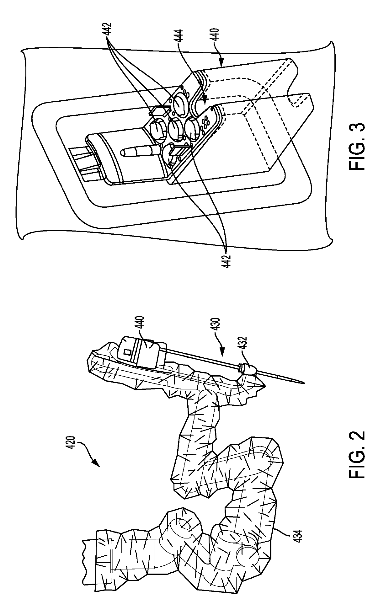
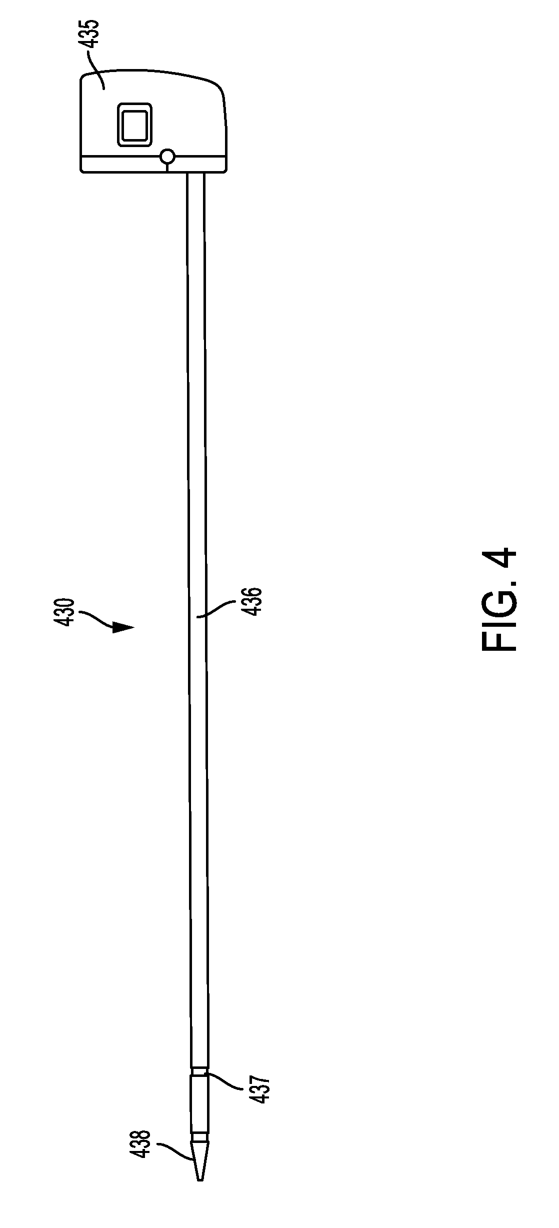
[0008]The system can vary in a number of ways. For example, the end effector can include a cutting element that is advanced through the end effector. The at least one visual indicator can also be configured to indicate a travel speed of the cutting element. The at least one visual indicator can include a plurality of markings spaced apart along at least one of the shaft and the end effector. In another example, the at least one visual indicator can include a grid pattern formed on the end effector. In still another example, the end effector can include a cutting element that is advanced through the end effector and a plurality of cut-outs that are formed in the end effector, enabling viewing of the cutting element therethrough as the cutting element is advanced through the end effector. The cutting elements can also include a grid pattern formed therein that is visible through the plurality of cut-outs. In another example, the electromechanical tool can include a housing on a proximal end of the shaft that couples to a tool driver on a distal end of the electromechanical arm. The tool driver can include a plurality of motors for actuating the end effector. The system can also include at least one camera configured to visually measure the action of the end effector.
[0010]The robotic system can have numerous variations. For example, the controller can also be configured to compare an actual speed of advancement of a cutting element moving through the end effector to a threshold speed, and to decrease a speed of the cutting element when the actual speed reaches the threshold speed. In another example, the at least one visual indicator includes a grid pattern formed on the end effector. The at least one visual indicator can also include openings along at least one of the first and second jaws of the end effector. The at least one camera can be configured to view motion of a cutting element through the openings. The at least one visual indicator can also be indicative of a length scale. The robotic system can also include a proximity zone at a distal end of the end effector. The controller can be configured to reduce a speed of advancement of a cutting element through the end effector when the cutting element reaches the proximity zone.
[0015]In another embodiment, a surgical robotic system can be provided that includes an electromechanical arm configured for movement in multiple axes. An electromechanical tool is configured to couple to the electromechanical arm and has an elongate shaft with an end effector coupled to a distal end thereof. A controller is configured to control movement of the electromechanical arm and to control actuation of the end effector on the electromechanical tool. The electromechanical tool includes a pre-set motion control threshold, and the controller is configured to prevent the electromechanical tool from exceeding the pre-set motion control threshold when the controller actuates at least one of the electromechanical arm and the electromechanical tool.
[0017]In another aspect, a surgical method is provided that includes causing a controller on a surgical robotic system to transmit input instructions to an electromechanical tool to thereby move the tool. The electromechanical tool has a pre-set motion control threshold, and the controller is configured to prevent the electromechanical tool from exceeding the pre-set motion control threshold when the controller moves the tool.

Problems solved by technology

For example, traditional minimally invasive surgical instruments often deny the surgeon the flexibility of tool placement found in open surgery.
Difficulty is experienced in approaching the surgical site with the instruments through the small incisions.
Additionally, the added length of typical endoscopic instruments often reduces the surgeon's ability to feel forces exerted by tissues and organs on the end effector.
Furthermore, coordination of the movement of the end effector of the instrument as viewed in the image on the television monitor with actual end effector movement is particularly difficult, since the movement as perceived in the image normally does not correspond intuitively with the actual end effector movement.
Accordingly, lack of intuitive response to surgical instrument movement input is often experienced.
Such a lack of intuitiveness, dexterity and sensitivity of endoscopic tools has been found to be an impediment in the increased the use of minimally invasive surgery.

Method used


Image

  • Robotic visualization and collision avoidance
  • Robotic visualization and collision avoidance
  • Robotic visualization and collision avoidance

Examples


Embodiment Construction

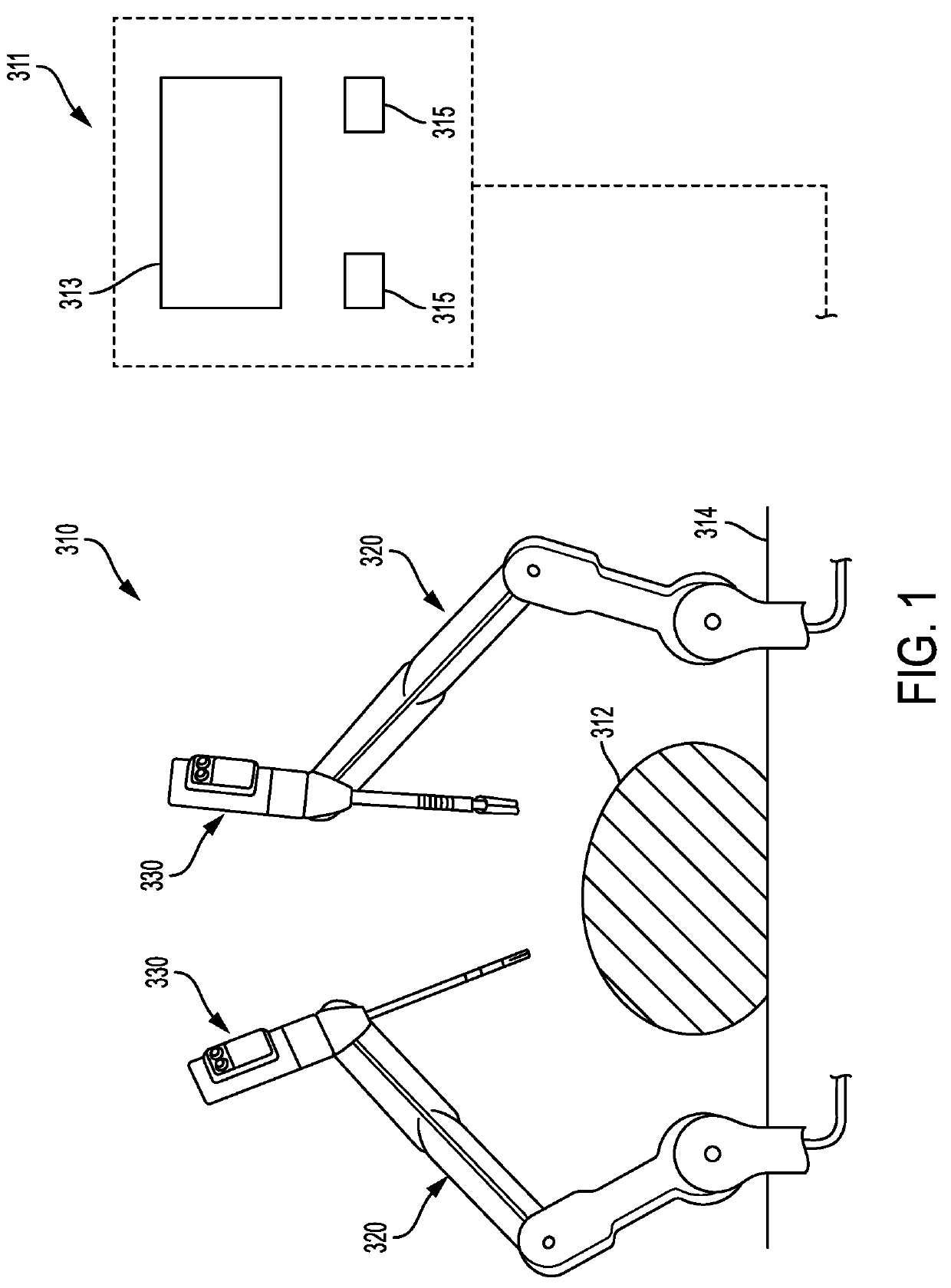
[0041]Certain exemplary embodiments will now be described to provide an overall understanding of the principles of the structure, function, manufacture, and use of the devices and methods disclosed herein. One or more examples of these embodiments are illustrated in the accompanying drawings. Those skilled in the art will understand that the devices and methods specifically described herein and illustrated in the accompanying drawings are non-limiting exemplary embodiments and that the scope of the present invention is defined solely by the claims. The features illustrated or described in connection with one exemplary embodiment may be combined with the features of other embodiments. Such modifications and variations are intended to be included within the scope of the present invention.

[0042]Further, in the present disclosure, like-named components of the embodiments generally have similar features, and thus within a particular embodiment each feature of each like-named component is...


PUM


Abstract

Methods and devices are provided for robotic surgery, and in particular for controlling various motions of a tool based on visual indicators. In general, a surgical tool can include an elongate shaft and an end effector coupled to a distal end of the elongate shaft and including first and second jaws. The tool can have at least one visual indicator disposed thereon and configured to indicate a size, position, or speed of movement of the tool or components of the tool.

Description

FIELD OF THE INVENTION[0001]Methods and devices are provided for robotic surgery, and in particular for visualizing, controlling, and collision avoidance in robotic tools.BACKGROUND OF THE INVENTION[0002]Minimally invasive surgical (MIS) instruments are often preferred over traditional open surgical devices due to the reduced post-operative recovery time and minimal scarring. Laparoscopic surgery is one type of MIS procedure in which one or more small incisions are formed in the abdomen and a trocar is inserted through the incision to form a pathway that provides access to the abdominal cavity. The trocar is used to introduce various instruments and tools into the abdominal cavity, as well as to provide insufflation to elevate the abdominal wall above the organs. The instruments and tools can be used to engage and / or treat tissue in a number of ways to achieve a diagnostic or therapeutic effect. Endoscopic surgery is another type of MIS procedure in which elongate flexible shafts ar...

Claims


Application Information

Patent Timeline
Patent Type & Authority Patents(United States)
IPC IPC(8): A61B34/30A61B17/072A61B90/00A61B34/37A61B17/32A61B17/00
CPCA61B34/37A61B34/30A61B17/32A61B90/06A61B17/07207A61B2090/061A61B2017/00119A61B2017/07278A61B2090/3937A61B2017/07271A61B2017/07285A61B2017/00017A61B2090/0811
Inventor YATES, DAVID C.HARRIS, JASON L.SHELTON, IV, FREDERICK E.ECKERT, CHAD E.
Owner CILAG GMBH INT
Why Eureka
Try Eureka