
Coating method and coating device

a coating device and coating technology, applied in the direction of coatings, liquid surface applicators, printing, etc., can solve the problems of inability to control the coating operation, the drying operation cannot keep up with the coating speed, and the coating speed is fast, so as to achieve high precision in straightness and fast coating speed

Active Publication Date: 2019-09-17
METAL INDS RES & DEV CENT
View PDF10 Cites 0 Cited by
  • Summary
  • Abstract
  • Description
  • Claims
  • Application Information

AI Technical Summary

Benefits of technology

[0008]The objective of the invention is to provide a coating method and a coating device to solve the problems that the speed of the fixed wire bar is fast and that high precisions in straightness and the cylindricity are required for the rotating wire bar.
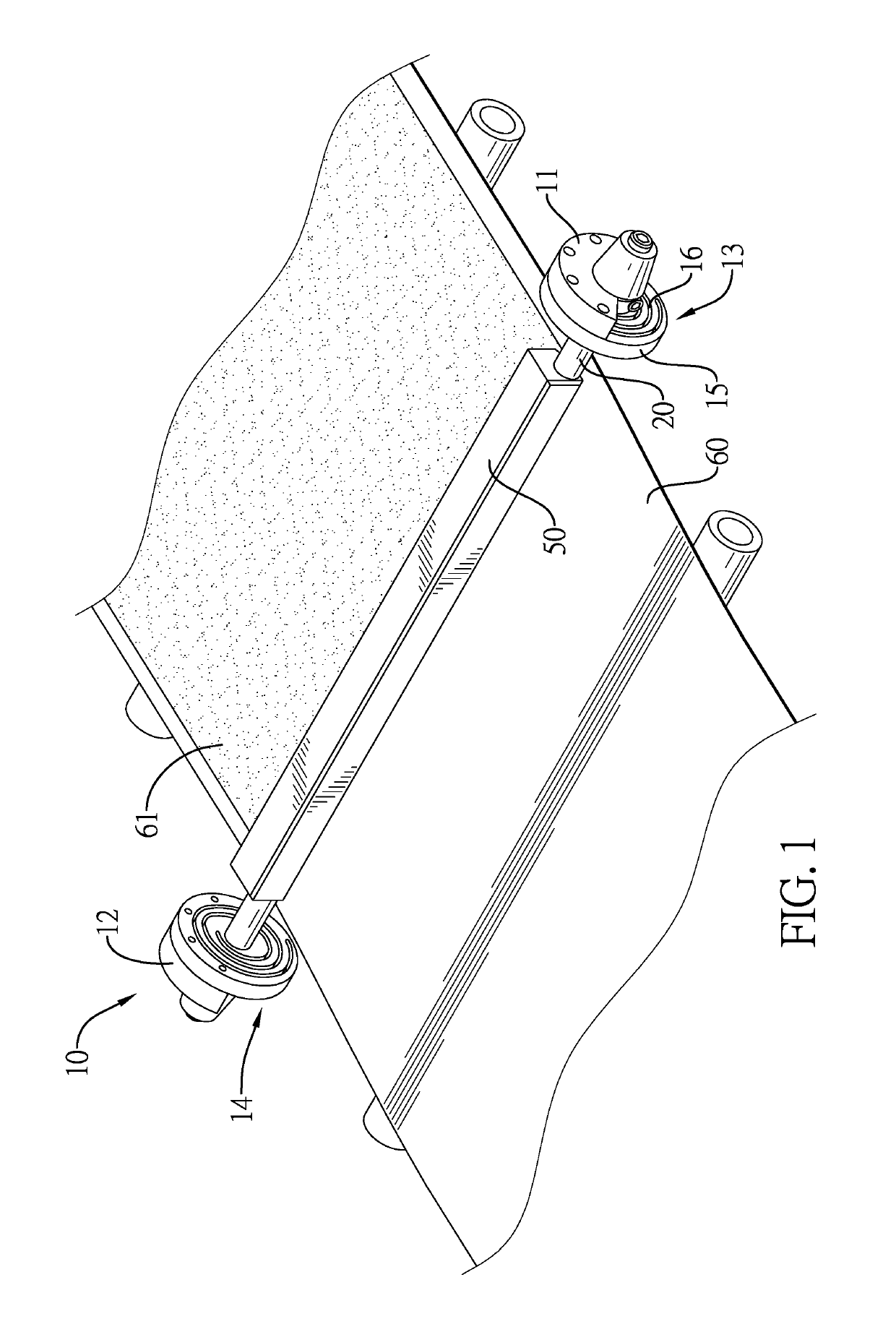
[0011]Accordingly, the wire bar driven by the rotation adjusting module can be rotated reciprocatingly. The second rotational speed of the wire bar is far faster than the first rotational speed of the wire bar. When the wire bar is rotated at the first rotational speed, the tangential direction of the wire bar at the connecting area between the wire bar and the web is opposite to the moving direction of the web. The relative speed between the wire bar and the film is increased. On the premise that the thickness of the film is controlled accurately, the coating speed of the wire bar can be decreased for controlling the output of the coating operation.
[0012]When the wire bar is rotated at the second rotational speed, the second rotational speed of the wire bar is far faster than the first rotational speed of the wire bar. The wire bar can be restored quickly and drives the ink to splash at the high speed. Compounds in the ink may be spread evenly for increasing the uniformity of the compounds in the ink. The connecting area between the wire bar and the film can be controlled by the reciprocating rotation of the wire bar. The precision requirements on the straightness and the cylindricity of the wire bar are decreased.

Problems solved by technology

The shortcoming of the fixed type wire bar is that the speed of the coating is fast and the drying operation cannot keep up with the coating speed.
The output of the coating operation cannot be controlled, causing increase of the stock of the coating operation.
In addition, the space needed for the factory and the facilities and the cost of the drying operation are increased for keeping up with the coating operation.
If the straightness and the cylindricity of the wire bar are inaccurate, the thickness of the film is not uniform.

Method used


Image

  • Coating method and coating device
  • Coating method and coating device
  • Coating method and coating device

Examples


Embodiment Construction

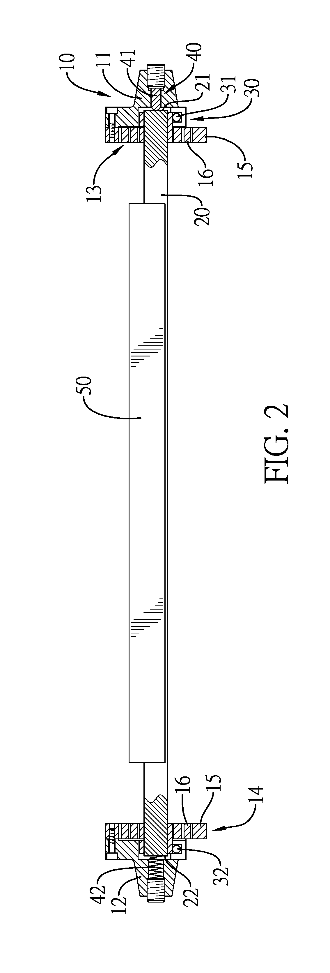
[0025]A coating method for using a coating device to coat a film 61 on a web 60 comprises a preparing step and a reciprocating rotating step. The preparing step comprises preparing a coating device. With reference to FIG. 5, a wire bar 20 of the coating device is rotated on the web 60 at a first rotational speed for coating the film 61 on the web 60. In a process of rotating the wire bar 20 at the first rotational speed, a tangential direction of the wire bar 20 at a connecting area between the wire bar 20 and the web 60 is opposite to a moving direction of the web 60. Then, the wire bar 20 of the coating device is rotated to an original position at a second rotational speed. In a process of rotating the wire bar 20 at the second rotational speed, the tangential direction of the wire bar 20 at the connecting area between the wire bar 20 and the web 60 is same to the moving direction of the web 60. The wire bar 20 is reciprocatingly rotated at the first rotational speed and the secon...


PUM


Abstract

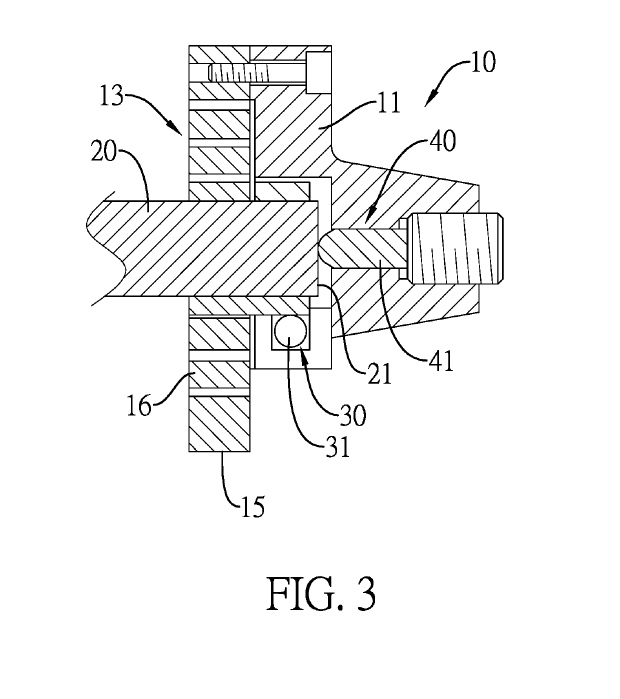
A coating method has a reciprocating rotating step. A wire bar is rotated at a first rotational speed for coating a film on a web. In a process of rotating the wire bar at the first rotational speed, a tangential direction of the wire bar at a connecting area between the wire bar and the web is opposite to a moving direction of the web, and then the wire bar is rotated to restore to an original position at a second rotational speed. Meanwhile, the tangential direction is changed and is same to the moving direction of the web. The second rotational speed is far faster than the first rotational speed. A coating device has a base, the wire bar disposed across the base, and a rotation adjusting module connected to the wire bar for driving the wire bar to rotate reciprocatingly.

Description

BACKGROUND OF THE INVENTION1. Field of the Invention[0001]The present invention relates to a coating method and a coating device, and more particularly to a coating method and a coating device that may effectively control the coating thickness and the coating uniformity.2. Description of Related Art[0002]Coating by a wire bar is a common coating method. The thickness of a film coated on a web is controlled by the diameter and the density of a wire wound on the wire bar. The U.S. Pat. No. 8,304,027 discloses a single wire bar. The wire bar is fixed and is not rotated for coating a thin and uniform film. The shortcoming of the fixed type wire bar is that the speed of the coating is fast and the drying operation cannot keep up with the coating speed. The output of the coating operation cannot be controlled, causing increase of the stock of the coating operation. In addition, the space needed for the factory and the facilities and the cost of the drying operation are increased for keepi...

Claims


Application Information

Patent Timeline
Patent Type & Authority Patents(United States)
IPC IPC(8): B05D1/00B05D1/28B05C1/08
CPCB05C1/0826B05D1/28B05C1/0808B05C1/0821B05C1/0852B05C11/025B41J2/01
Inventor LIU, KUAN-CHIHLIN, SHI-WEI
Owner METAL INDS RES & DEV CENT
Learn More