
Wire EDM

A wire electric discharge machine and electric discharge circuit technology, applied in electric machining equipment, metal machining equipment, circuits, etc., can solve the problems of longer machining time, recovery, and time spent on removing short circuits, so as to improve the accuracy of straightness, improve the Processing speed and the effect of improving processing efficiency

Active Publication Date: 2018-04-06
FANUC LTD
View PDF14 Cites 0 Cited by
  • Summary
  • Abstract
  • Description
  • Claims
  • Application Information

AI Technical Summary

Problems solved by technology

In these methods, a detection circuit composed of a coil, a voltage dividing resistor, etc., and an analog circuit for processing an analog signal output from the detection circuit are required. Therefore, there are problems in that the structure is complicated and expensive, or the detection circuit needs to be used. , The correction method for correcting the error of the analog circuit
Conversely, if the machining current is not flowing or the machining current is reduced, the machining debris between the electrodes cannot be removed, and the wire and the workpiece come into contact with each other, resulting in a complete short circuit state.
As a result, it is necessary to move the relative position between the wire and the workpiece, expand the distance between the poles to release the short-circuit state, and it takes time to release the short-circuit, so the processing time becomes longer, or in the worst case, the short-circuit state No machining current flows, or only a small machining current flows, therefore, it is impossible to recover from the short-circuit state, and the machining stops

Method used


Image

  • Wire EDM
  • Wire EDM
  • Wire EDM

Examples


Embodiment Construction

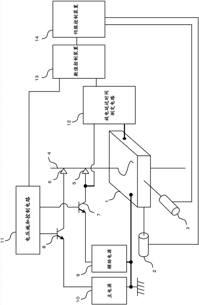
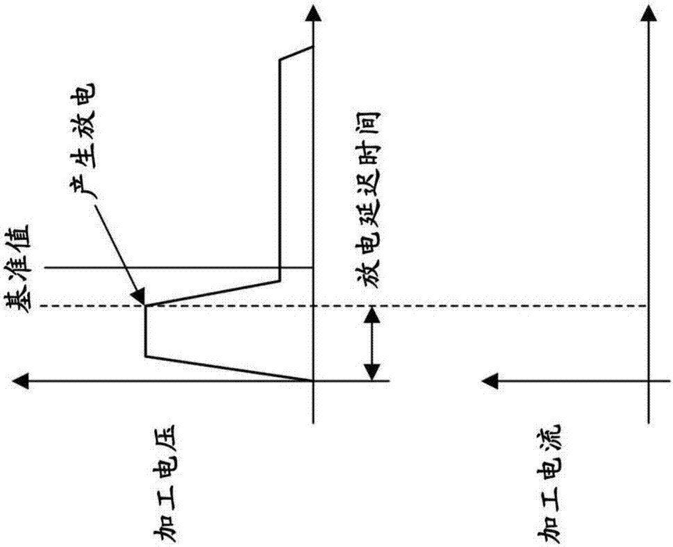
[0050] below, with Figure 1 Embodiments of the present invention will be described together. figure 1 It is a block diagram illustrating the wire electric discharge machine of the present invention. In the present invention, using the discharge delay time, the state between the poles is classified into a short circuit state, a situation with a small gap between the poles, and a situation with a large gap between the poles, and accordingly it is determined from the main discharge circuit (including the main power supply) 10. The magnitude of the machining current supplied by the circuit of the switching element 8).

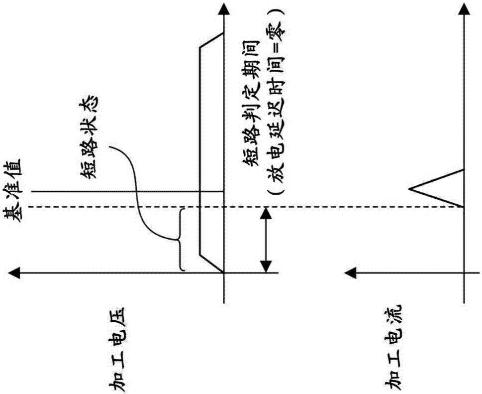
[0051] After a predetermined time has elapsed since the auxiliary discharge circuit (circuit including the auxiliary power supply 9 and the switching element) starts to apply the machining voltage to the inter-electrodes, in the case where the discharge delay time is zero (that is, in a state where there is no discharge), it is judged that Because the electrodes...


PUM


Abstract

The present invention relates to a wire electric discharge machine in which the state between electrodes is classified into a short-circuit state, a case in which the amount of inter-electrode gap is small, and a case in which the amount of inter-electrode gap is large, using the discharge delay time. Correspondingly, the magnitude of the machining current supplied from the main discharge circuit is determined. When the discharge delay time is zero (that is, the state where there is no discharge) after a predetermined time has elapsed since the application of the machining voltage from the auxiliary discharge circuit to the inter-electrode space, it is judged that the inter-electrode space is in a state of being short-circuited by machining debris. , By supplying the machining current from the main discharge circuit to the inter-electrode during short circuit, the machining debris is removed, thereby preventing a complete short circuit state, and at the same time improving the machining efficiency and thus increasing the machining speed.

Description

technical field [0001] The present invention relates to a wire electric discharge machine. Background technique [0002] When electrical discharge machining is performed by a wire electrical discharge machine, the shape of the machined surface becomes a shape in which a substantially wire shape is reproduced. Basically, as the distance between the upper and lower guides increases, the amount of deflection at the central portion tends to increase, so the straightness accuracy of the processed surface tends to deteriorate as the plate thickness increases. [0003] In order to solve this problem, in Japanese Patent Application Publication No. 62-152616, Japanese Patent Application Publication No. 1-121127, Japanese Patent Application Publication No. 7-171716, Japanese Patent Application Publication No. 7-60548, Japanese Patent Application Publication No. 2004-50298 Publications, WO93 / 01017, WO2007 / 032114, and WO2008 / 050404 describe the method of measuring the machining current...

Claims


Application Information

Patent Timeline
Patent Type & Authority Patents(China)
IPC IPC(8): B23H7/04B23H7/20
CPCA63B41/08A63B45/00
Inventor 古田友之依田慎司川原章义中岛廉夫
Owner FANUC LTD
Learn More