Drilling tool and processing method of annular hole of drilling tool

A technology for annular holes and drilling tools, which is applied in drilling tool accessories, metal processing equipment, drilling/drilling equipment, etc. It can solve the problems of stuck drill, low cutting efficiency, and drilling tools deviate from the machining center line, etc., and achieve good cutting Guidance, good cutting stability, and high straightness accuracy

Inactive Publication Date: 2018-11-13
SHANGHAI DIANJI UNIV
View PDF6 Cites 0 Cited by
  • Summary
  • Abstract
  • Description
  • Claims
  • Application Information

AI Technical Summary

Problems solved by technology

However, when the workpiece to be processed is not a rotating body and cannot be clamped and rotated, the straightness error of the drilling hole is very large, which cannot meet the processing requirements; at the same time, as the processing axis deviates farther and farther from the center, the swing range of the drilling tool becomes larger and larger. The larger the size, the interference between the ring hole and the drill pipe, the material core and the drill pipe will make it impossible to continue the drilling process, and in severe cases, the drill will be stuck; therefore, if the workpiece does not rotate, the current ring hole drill cannot complete deep hole processing
[0006] 2. When the single-groove single-cutter ring hole drill is processed, the workpiece only bears the cutting force on one side, and the cutting efficiency is low; at the same time, because the single knife and the three guide support blocks are evenly distributed at 90°, the diameter of the support circle surrounded by the guide support blocks Constant, when the tool tip is worn, the diameter of the ring hole to be processed becomes smaller, which may easily cause drill sticking and cannot continue processing
[0007] 3. Although the cutting force of the symmetrical annular drill with four slots and four knives (two slots and two knives, and six slots and six knives) is evenly distributed and the cutting efficiency is improved, the number of even-numbered blades and multiple even-numbered guide support blocks are still uniform on the circumference The diameter of the support circle surrounded by the guide support block is still a fixed value. When the blade wears, the outer diameter of the ring hole will decrease, which will cause the guide support block to stick
[0008] 4. The above two ring hole drilling tools also lack good drilling guidance due to the unreasonable shape and installation of the blade, and there is a problem of poor guiding accuracy during the processing, which will cause the drilling tool to deviate from the machining center line during drilling, resulting in machining The straightness of the hole is poor, causing drill sticking in severe cases

Method used


Image

  • Drilling tool and processing method of annular hole of drilling tool
  • Drilling tool and processing method of annular hole of drilling tool
  • Drilling tool and processing method of annular hole of drilling tool

Examples


Embodiment Construction

[0026] In the following description, numerous specific details are given in order to provide a more thorough understanding of the present invention. It will be apparent, however, to one skilled in the art that the present invention may be practiced without one or more of these details. In other examples, some technical features known in the art are not described in order to avoid confusion with the present invention.

[0027] In order to thoroughly understand the present invention, detailed steps and detailed structures will be provided in the following description, so as to illustrate the technical solution of the present invention. Preferred embodiments of the present invention are described in detail below, however, the present invention may have other embodiments besides these detailed descriptions.

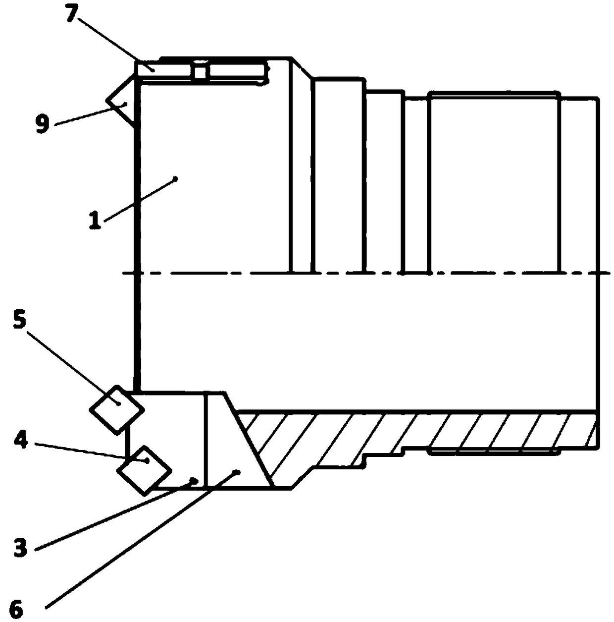
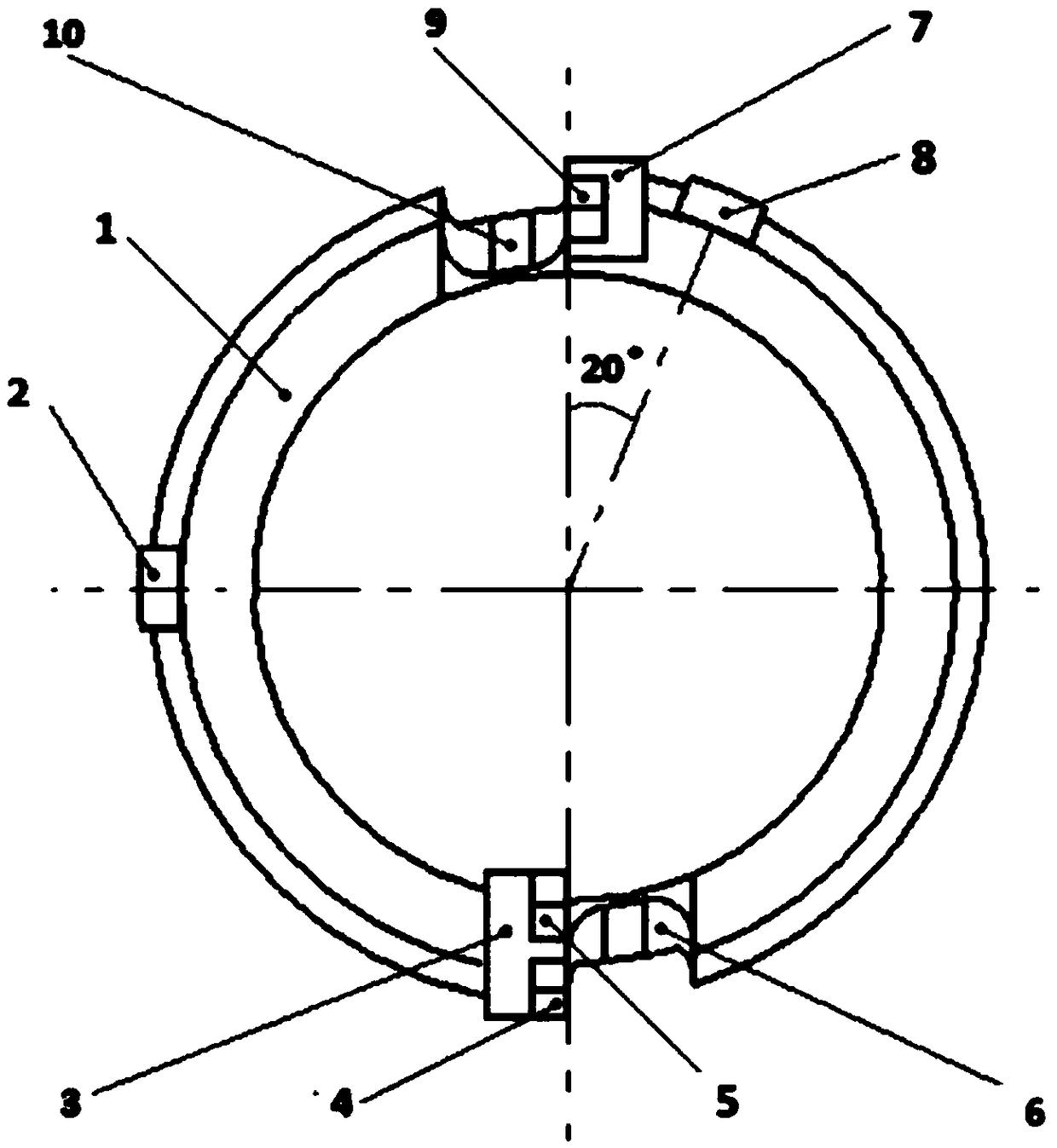
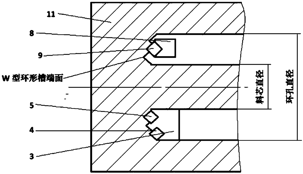
[0028] Such as Figure 1-3 As shown, the present invention provides a drilling tool for processing annular holes. The drilling tool body is a circular tube structure, and t...


PUM


Abstract

The invention provides a drilling tool and a processing method of an annular hole of the drilling tool. A drilling tool body is of a tubular structure, two chip guide slots and two tool aprons are symmetrically formed in the front end of the drilling tool body circumferentially, a small tool apron is mounted next to the first chip guide slot, and a middle blade is mounted in the middle position ofthe small tool apron; a large tool apron is mounted next to the second chip guide slot, an outer blade and an inner blade are mounted in a spaced manner parallelly on the large tool apron, and the inner blade is located between the outer blade and the axis of the drilling tool body; on a cutting radius, the middle blade, the outer blade and the inner blade are arranged in a staggered manner; twoguiding supporting blocks are arranged at the front end of the drilling tool body circumferentially, the first guiding supporting block is rotated clockwise at 20 degrees backward from the small toolapron, the second guiding supporting block is rotated clockwise at 90 degrees from the big tool apron, and the two guiding supporting blocks are distributed at an included angle of 110 degrees circumferentially. The straightness of the annular hole processed by the drilling tool is relatively high in precision, the condition that a supporting block jams the drilling tool easily in the drilling process is avoided, and the drilling tool is high in cutting efficiency and good in cutting stability.

Description

technical field [0001] The invention relates to a ring-shaped deep hole processing method and a special ring-hole drilling tool, in particular to a ring-shaped deep hole processing method in which only the drilling tool is rotated and the workpiece does not need to be rotated during the processing process. Background technique [0002] Annular deep hole processing method (also known as annular drill, trepanning drill) is used to process deep holes with larger diameters. Since only one annular deep hole is cut out during the processing process, the cylindrical core in the center of the annular hole can be completely taken out and can be Also take advantage of it. This method saves metal materials and reduces power consumption, and is often used for deep hole processing of large workpieces. [0003] The blade of the ring hole drilling tool is installed on the tool seat, and the tool seats are distributed around the cylindrical drill body, and there is a chip guide groove besi...

Claims


Application Information

Patent Timeline
Patent Type & Authority Applications(China)
IPC IPC(8): B23B51/04B23B35/00
CPCB23B51/04B23B35/00
Inventor 汤子尧辛绍杰
Owner SHANGHAI DIANJI UNIV
Why Eureka
Try Eureka