Methods of manufacturing axisymmetric body and axisymmetric product

a technology of which is applied in the field of methods of manufacturing axisymmetric body and axisymmetric product, can solve the problems of high cost of casting mold manufacturing, waste of large amount of materials, etc., and achieve the effect of wide width

Inactive Publication Date: 2019-09-17
KAWASAKI HEAVY IND LTD
View PDF16 Cites 1 Cited by
  • Summary
  • Abstract
  • Description
  • Claims
  • Application Information

AI Technical Summary

Benefits of technology

[0015]The present invention can manufacture the axisymmetric body including the flange portion having a relatively wide width by using the laser metal deposition.CITATION LISTPatent Literature

Problems solved by technology

However, the casting requires high cost for manufacturing a mold, and the cutting wastes a large amount of materials.

Method used


Image

  • Methods of manufacturing axisymmetric body and axisymmetric product
  • Methods of manufacturing axisymmetric body and axisymmetric product
  • Methods of manufacturing axisymmetric body and axisymmetric product

Examples


Embodiment Construction

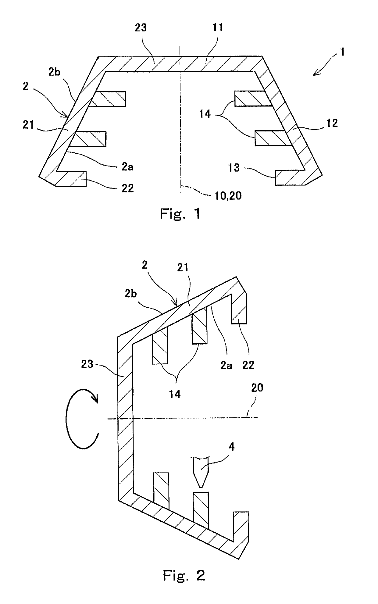
[0027]A method of manufacturing an axisymmetric body according to one embodiment of the present invention is a method of manufacturing an axisymmetric body 1 having a shape that is symmetrical around a central axis 10 as shown in FIG. 1. In the present embodiment, the axisymmetric body 1 is hollow and opens in an axial direction (downward direction in FIG. 1). Specifically, the axisymmetric body 1 includes: a ceiling wall 11; a tapered peripheral wall 12 spreading from a peripheral portion of the ceiling wall 11; two first flange portions 14 (each corresponding to a flange portion of the present invention) projecting inward in a radial direction from an intermediate portion of the peripheral wall 12; and a second flange portion 13 projecting inward in the radial direction from a tip end of the peripheral wall 12.

[0028]However, the shape of the axisymmetric body 1 is not limited to the shape shown in FIG. 1. For example, the peripheral wall 12 of the axisymmetric body 1 may be straig...


PUM

PropertyMeasurementUnit
diameteraaaaaaaaaa
heightaaaaaaaaaa
thickaaaaaaaaaa

Abstract

First, an annular first layer including a plurality of beads and having a width that is not less than twice a width of the bead is formed by laser metal deposition on a peripheral surface of a base metal, the peripheral surface facing outward or inward in a radial direction. Next, a plurality of annular height raising layers each including a plurality of beads are stacked on the first layer by the laser metal deposition. According to this configuration, an axisymmetric body including a flange portion having a relatively wide width can be manufactured while making a heat affected zone in the base metal extremely small.

Description

TECHNICAL FIELD[0001]The present invention relates to a method of manufacturing an axisymmetric body including a flange portion and a method of manufacturing an axisymmetric product from the axisymmetric body obtained by the above manufacturing method.BACKGROUND ART[0002]An axisymmetric body including a flange portion is manufactured by, for example, casting or cutting of a columnar or thick cylindrical raw material. However, the casting requires high cost for manufacturing a mold, and the cutting wastes a large amount of materials.SUMMARY OF INVENTIONTechnical Problem[0003]Therefore, it is desired that a flange portion be formed later at a base metal. For example, it can be thought that a ring-shaped plate is joined to a tubular base metal by full penetration welding. However, since the amount of heat input to the base metal in the welding is extremely large, a heat affected zone (HAZ) in the base metal becomes large.[0004]Here, the heat affected zone in the base metal can be made ...

Claims


Application Information

Patent Timeline
Patent Type & Authority Patents(United States)
IPC IPC(8): B23K26/00B23K26/144B23K26/70B22F5/10B22F3/105B33Y70/00B23K26/21B33Y10/00B33Y40/00B23K26/342B22F5/00C22C1/04B23K103/14
CPCB23K26/702B22F3/1055B23K26/144B33Y40/00B22F5/10B23K26/703B33Y10/00B23K26/21B23K26/0093B23K26/342B33Y70/00B22F2005/005C22C1/0458B23K2103/14Y02P10/295Y02P10/25B22F10/25B23K26/34
Inventor TSUJI, TOSHIROKABE, YOSHIROIMAMURA, YOSHIHIDEIWASAKI, HAYATOKITANO, HIROSHI
Owner KAWASAKI HEAVY IND LTD
Why Eureka
Try Eureka