Strengthening system for beam-column connection in steel frame buildings to resist progressive collapse

a technology of steel frame buildings and strengthening systems, which is applied in the direction of building components, building types, constructions, etc., can solve the problems of missing the currently available beam-column connection, unable to resist progressive collapse of steel frame buildings, and many steel buildings have witnessed progressive collapse. , to achieve the effect of reducing the risk of falling

Active Publication Date: 2019-09-17
KING SAUD UNIVERSITY
View PDF21 Cites 8 Cited by
  • Summary
  • Abstract
  • Description
  • Claims
  • Application Information

AI Technical Summary

Benefits of technology

[0006]The strengthening system for beam-column connections in steel frame buildings to resist progressive collapse helps to mitigate progressive collapse in the event of accidental column loss by using a system of rippled steel plates reinforcing the beam-column connection. Various configurations of rippled steel plates are provided to connect in-plane and transverse beams at a joint. In the event of severe damage caused to a column of a steel framed building, the upper joints of the damaged column undergo downward movement. The rippled plates at the joint straighten during the initial downward movement, and resist further downward movement after complete straightening of the ripples. This helps in the development of catenary action in steel beams. The proposed system is simple, fast to construct, demountable, and easy to repair / replace after damage caused by blast loads.

Problems solved by technology

Although the plastic behavior of steel provides additional security in extreme loading situations, several steel buildings have witnessed progressive collapse due to exposure to blast loads.
“Progressive collapse” is the propagation of an initial local failure from one part to the adjoining parts, and eventually collapse of the entire building or a large part of it.
In the event of localized failures due to blast or seismic events, steel-framed structures are required to have well-defined redundancies so that alternative load paths are available through the formation of catenary action, which is greatly lacking in currently available beam-column connections.

Method used


Image

  • Strengthening system for beam-column connection in steel frame buildings to resist progressive collapse
  • Strengthening system for beam-column connection in steel frame buildings to resist progressive collapse
  • Strengthening system for beam-column connection in steel frame buildings to resist progressive collapse

Examples


first embodiment

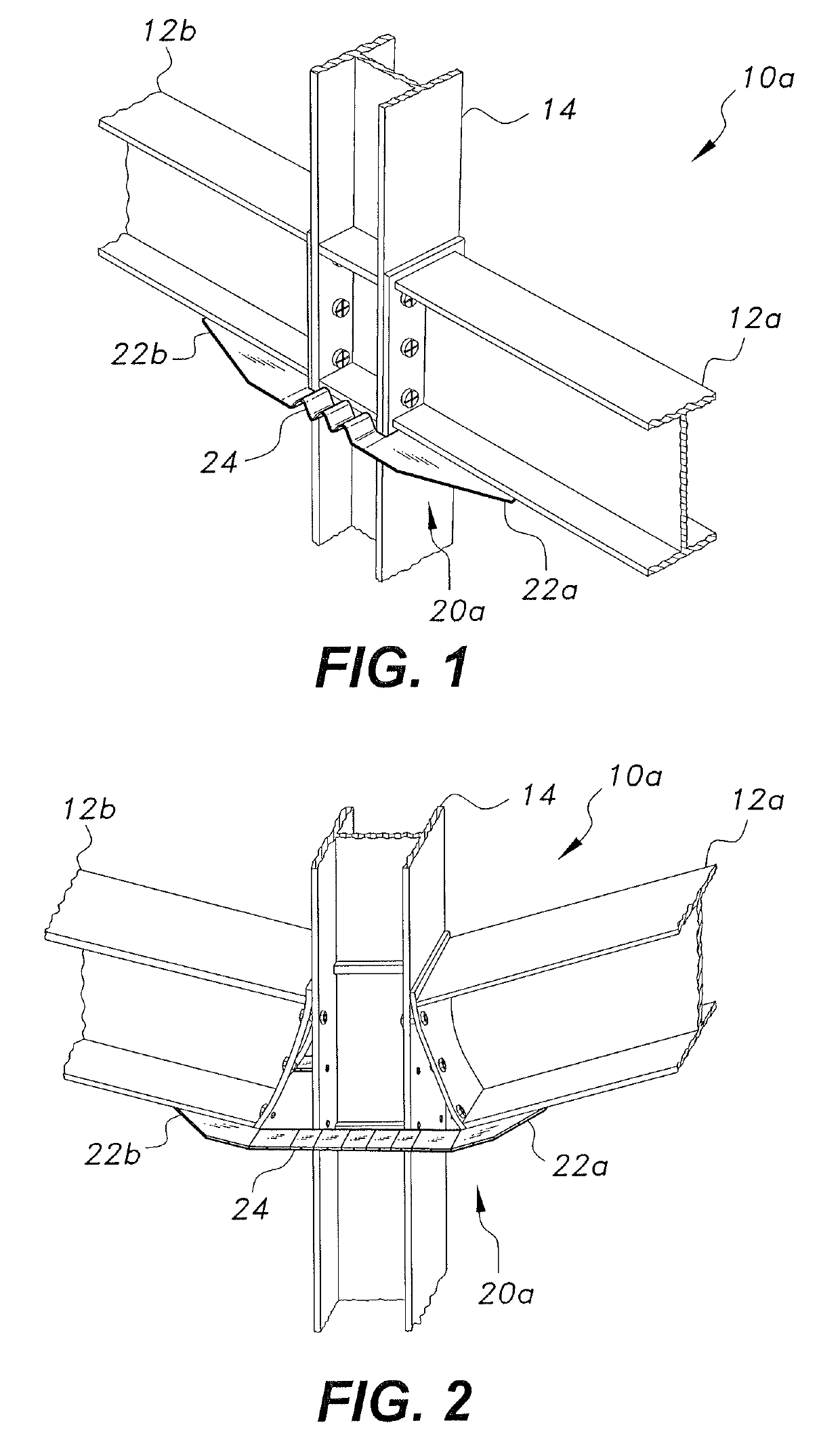
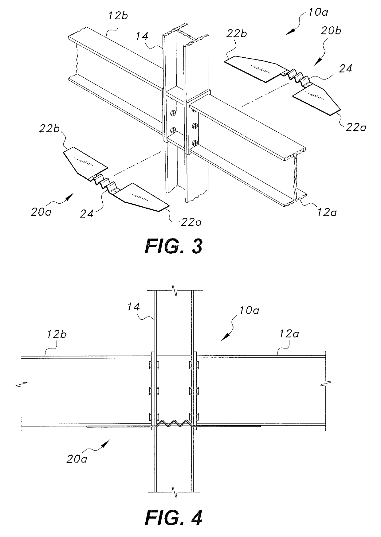
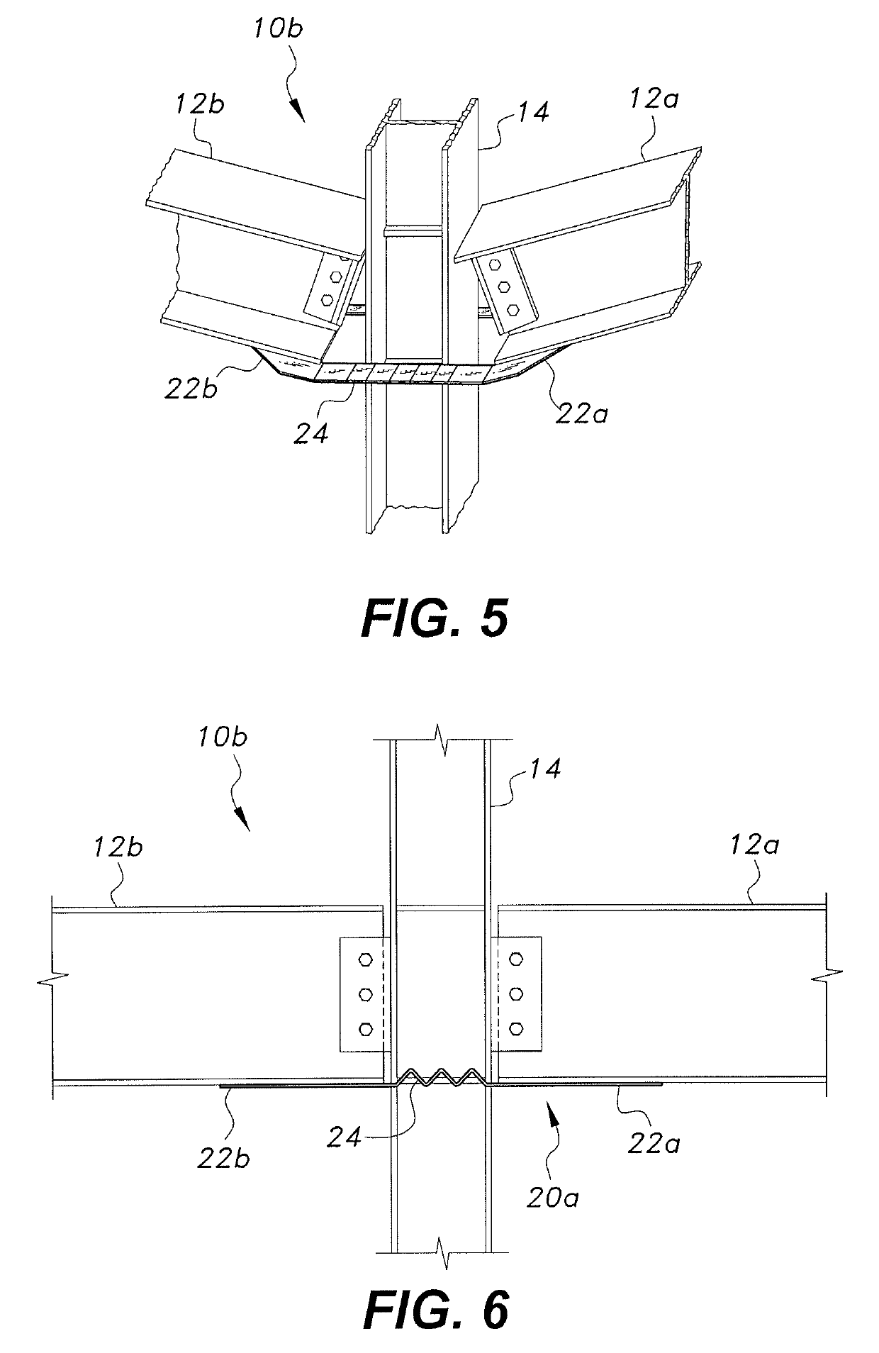
[0038]FIGS. 1-4 depict the strengthening system for beam-column connection in steel frame buildings to resist progressive collapse for a semi-rigid connection. As seen in FIGS. 1-4, two rippled plates 20a, 20b are secured across a bottom of a semi-rigid beam-column connection 10a, or beam-column joint. The rippled plates' 20 first resistive measure is impulse dissipation by spreading the large initial force caused by the beam dropping down to a lower force over a longer period of time. This is achieved through straightening of the ripples 24 on the plates 20a, 20b. The force from the plates 20a, 20b counters a separating force at the lower edge of the beams 12a, 12b. Once the ripples 24 are straightened and a large amount of the force on the joint 10a has been dispersed, the tensile strength of the straightened plate will counteract the remaining force, thus retaining the connection between the beams 12a, 12b and the column 14. The beams 12a, 12b will then be able to support the col...

fifth embodiment

[0052]FIGS. 17-20 depict the strengthening system for beam-column connection in steel frame buildings to resist progressive collapse. As seen in FIGS. 17-21, this embodiment is directed at an internal joint 10c connecting four perpendicular beams. Four rippled plates 50a, 50b, 50c, 50d are used to reinforce the joint, and each beam is connected to the two adjacent beams through the rippled plates. For example, beam 12a is connected to beams 12b and 12d by plates 50b and 50a, respectively. Each plate 50a, 50b, 50c, 50d includes a horizontally oriented rippled section 54 and two mounting portions 52a, 52b. The mounting portions 52a, 52b may be oriented at 45° from the rippled section 54 to align with the beams 12, as shown in FIG. 20. Each mounting portion 52a, 52b is connected to the lower flange of two adjacent, perpendicular beams at a location immediately next to the adjacent plate. FIG. 19 shows the plates 50a-d connected to the joint 10c from a top view. The edges of the four pl...


PUM


Abstract

The strengthening system for beam-column connections in steel frame buildings to resist progressive collapse helps to mitigate progressive collapse in the event of accidental column loss by using a system of rippled steel plates reinforcing the beam-column connection. Various configurations of rippled steel plates are provided to connect in-plane and transverse beams at a joint. In the event of severe damage caused to a column of a steel framed building, the upper joints of the damaged column undergo downward movement. The rippled plates at the joint straighten during the initial downward movement, and resist further downward movement after complete straightening of the ripples. This helps in the development of catenary action in steel beams. The proposed system is simple, fast to construct, demountable, and easy to repair / replace after damage caused by blast loads.

Description

BACKGROUND1. Field[0001]The disclosure of the present patent application relates to beam-column connections in steel frame buildings, and particularly to a strengthening system for beam-column connection in steel frame buildings to resist progressive collapse.2. Description of the Related Art[0002]The use of steel frames in building construction is quite popular, as it offers many advantages over traditional reinforced concrete, which include lower costs, sustainability, and flexibility. The use of prefabricated steel buildings takes advantage of offsite prefabrication to improve the speed of erection and independence from the weather. Additionally, cost control is achieved through increased productivity in its design, fabrication, and erection. A relatively shorter construction period helps in early possession of the building for use or rent and lowers financing costs. Other benefits of steel framed construction include large unsupported spans, slender columns resulting in maximizi...

Claims


Application Information

Patent Timeline
Patent Type & Authority Patents(United States)
IPC IPC(8): E04B1/24E04B1/98E04H9/04E04H9/02
CPCE04B1/2403E04H9/04E04B1/98E04H9/024E04B2001/2442E04B2001/2457E04B2001/2445E04B2001/2415E04B2001/2448
Inventor ABBAS, HUSAINAL-SALLOUM, YOUSEF A.ALMUSALLAM, TAREK H.ELSANADEDY, HUSSEIN MOHAMEDALRUBAIDI, MOHAMMAD
Owner KING SAUD UNIVERSITY
Why Eureka
Try Eureka