Roller chain

a technology of roller chain and roller, applied in the direction of driving chains, etc., can solve the problems of reducing the strength of the ring-like parts, exacerbate the problems, and the roller b>180/b> will be even more susceptible to local damage or the like, so as to reduce the noise generated, reduce the impact load, and minimize the deformation and damage of local plastics

Inactive Publication Date: 2019-09-17
TSUBAKIMOTO CHAIN CO
View PDF18 Cites 0 Cited by
  • Summary
  • Abstract
  • Description
  • Claims
  • Application Information

AI Technical Summary

Benefits of technology

[0005]However, each of the ring-like parts 180a that form the coil spring-like rollers 180 does not necessarily deform elastically in a uniform manner when the rollers 180 collide with the sprockets S. Elastic deformation occurs disproportionately and localizes in the large-diameter ring-like parts 180a that make contact with the sprockets S more frequently as shown in FIGS. 9A and 9B. Thus the large-diameter ring-like parts 180a are more susceptible to plastic deformation and damage, as a result of which life of the rollers 180 could be shortened.
[0006]When the large-diameter ring-like parts 180a undergo plastic deformation into an oval shape or the like, the rollers 180 can no longer rotate smoothly relative to the bushings 140. As this deteriorates the original function of the rollers, which is to reduce resistance between bushings and sprockets S, the rollers 180 will be even more susceptible to local damage or the like.

Problems solved by technology

As this deteriorates the original function of the rollers, which is to reduce resistance between bushings and sprockets S, the rollers 180 will be even more susceptible to local damage or the like.
To meet with the demands, for example the coil spring-like rollers 180 need to be formed from thinner spring wires, which only results in lowered strength of the ring-like parts 180a and exacerbates the problems described above.

Method used


Image

  • Roller chain
  • Roller chain
  • Roller chain

Examples


first embodiment

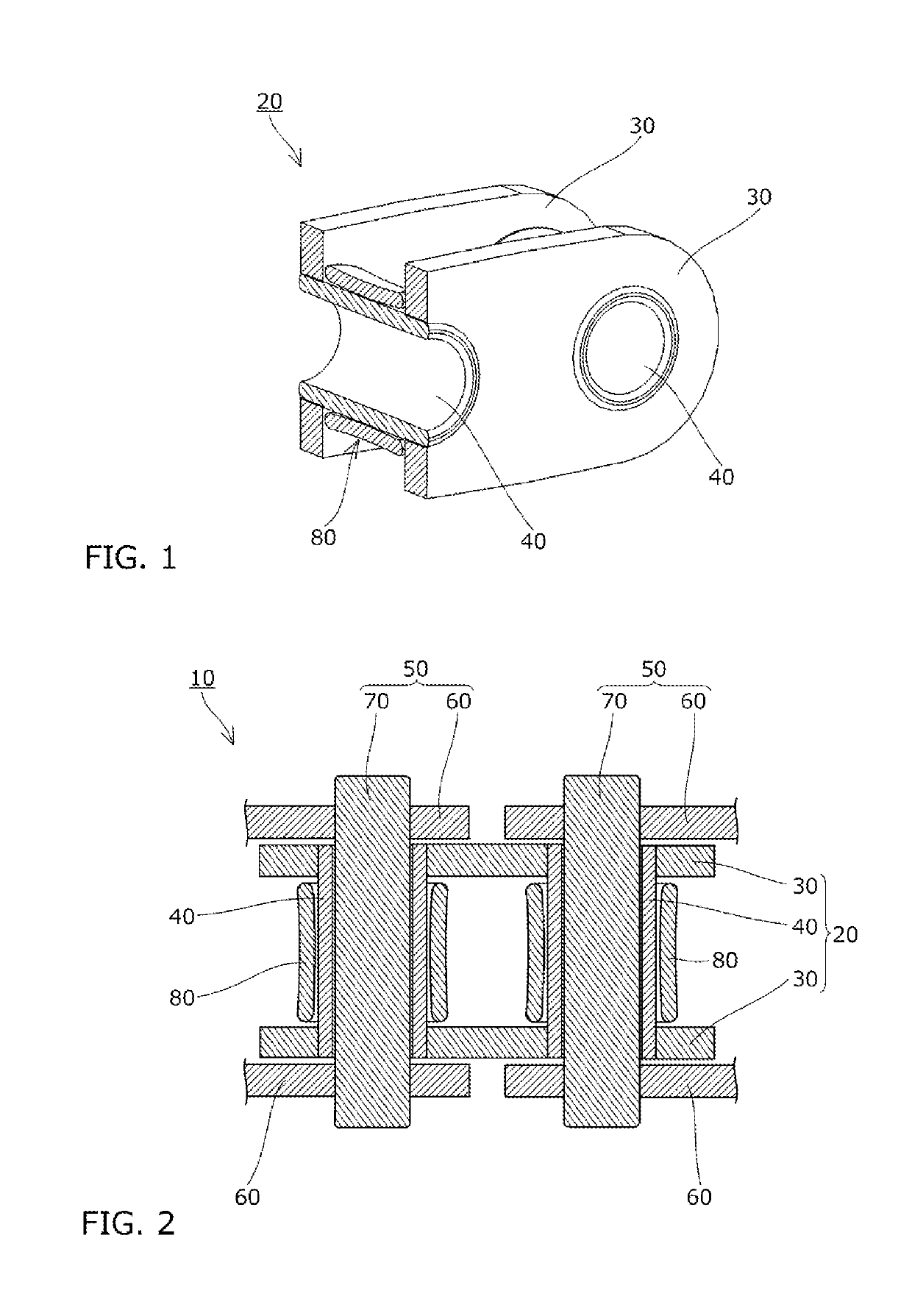
[0024]Hereinafter, a roller chain 10 according to the present invention will be described with reference to FIGS. 1 to 4.

[0025]The roller chain 10 of the first embodiment is configured as a timing chain used in a car engine and includes, as shown in FIGS. 1 and 2, a plurality of inner links 20 each made up of a pair of front and rear cylindrical bushings 40 connected to a pair of left and right inner plates 30, a plurality of outer links 50 each made up of pair of front and rear connecting pins 70 connected to a pair of left and right outer plates 60, and metal rollers 80 fitted on the bushings 40. These plurality of inner links 20 and outer links 50 are alternately and pivotably connected to each other along the longitudinal direction of the chain by inserting the connecting pins 70 in the bushings 40.

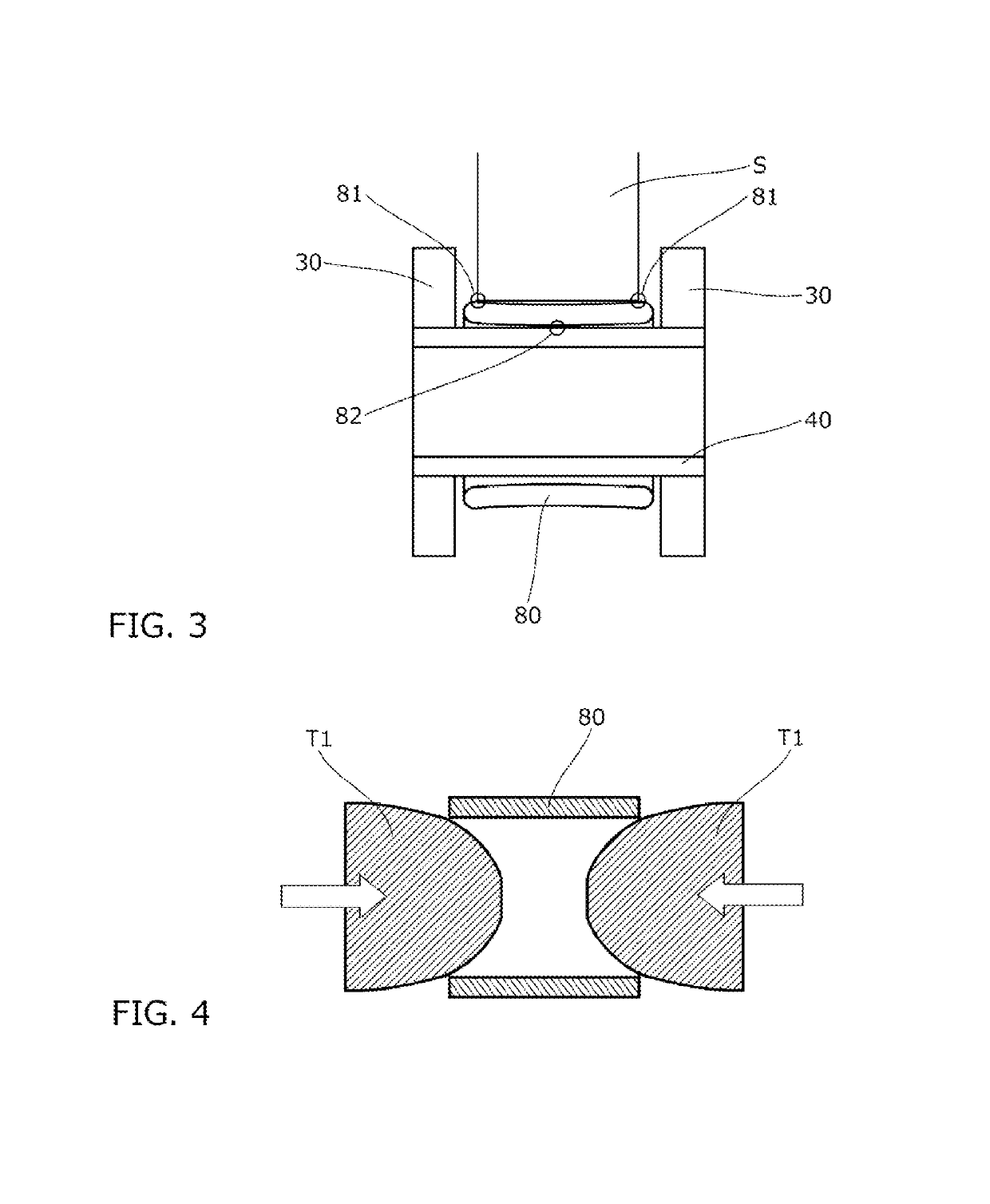
[0026]Each roller 80 is formed in a cylindrical shape tubularly connected continuously in axial and circumferential directions of the roller as shown in FIGS. 1 to 3.

[0027]Each roller...
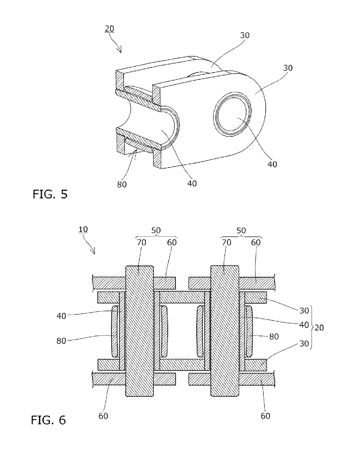
second embodiment

[0038]The roller 80 in the roller chain 10 of the second embodiment is formed in a cylindrical shape tubularly connected continuously in the axial and circumferential directions of the roller as shown in FIGS. 5 to 7.

[0039]Each roller 80 is curved in a barrel-like shape such as to bulge in the middle, so that the inner diameter at both ends of the roller is smaller than the inner diameter in the middle part of the roller, as well as the outer diameter at both ends of the roller is smaller than the outer diameter in the middle part of the roller.

[0040]The outer circumferential surface of the roller 80 is convexly curved such what the roller diameter increases smoothly from both axial ends of the roller toward the center of the roller.

[0041]The inner circumferential surface of the roller 80 is concavely curved such that the roller diameter increases smoothly from both axial ends of the roller toward the center of the roller.

[0042]The thickness of the roller 80 is substantially uniform...


PUM


Abstract

A roller chain with a simple structure is provided, which can mitigate impact load on rollers due to collision with sprockets and can lengthen roller life, as well as minimize interference between the sprockets and inner plates. A roller chain includes rollers that are formed in a cylindrical shape tubularly connected continuously in axial and circumferential directions of the rollers. Each of the rollers is curved such that an inner diameter at both ends thereof differs from that of a middle part, and that their outer diameter at both ends differs from that of the middle part, so that the rollers deform elastically when contacting sprockets S as the rollers are sandwiched between bushings and the sprockets.

Description

BACKGROUND OF THE INVENTION1. Field of the Invention[0001]The present invention relates to a roller chain formed by a plurality of inner links and outer links coupled together in an endless manner.2. Description of the Related Art[0002]Roller chains formed by a plurality of inner links, a plurality of outer links, and rollers are conventionally known. The inner links are each configured by coupling a pair of front and rear bushings to a pair of left and right inner plates. The outer links are each configured by coupling a pair of front and rear connecting pins to a pair of left and right outer plates. The rollers are fitted on the bushings. The inner links and outer links are alternately and pivotably coupled together in a longitudinal direction of the chain by inserting the connecting pins in the bushings.[0003]In such a roller chain, it is known that, when the chain runs, the rollers generate noise as they collide sprockets. It has been proposed, therefore, to fit rollers 180 form...

Claims


Application Information

Patent Timeline
Patent Type & Authority Patents(United States)
IPC IPC(8): F16G13/06
CPCF16G13/06
Inventor SANO, HIROKAZU
Owner TSUBAKIMOTO CHAIN CO
Why Eureka
Try Eureka