Method and system of measuring a transparent effect of transparent display

a transparent display and measurement method technology, applied in the field of display measurement, can solve the problems of inability to apply lcd and oled of prior art to all occasions, no standard measurement method and effective measurement device used to measure the transparent effect of transparent display, and no unified evaluation and comparison of transparent display products. achieve the effect of accurate and reliable measurement, easy and effective measurement of the transparent

Inactive Publication Date: 2019-09-17
SHENZHEN CHINA STAR OPTOELECTRONICS SEMICON DISPLAY TECH CO LTD
View PDF12 Cites 0 Cited by
  • Summary
  • Abstract
  • Description
  • Claims
  • Application Information

AI Technical Summary

Benefits of technology

[0007]An objective of the present invention is to provide a method of measuring a transparent effect of a transparent display, which can easily and effectively measure the transparent effect of the transparent display and can provide the basis for the comparison of the properties of the different transparent displays. The measurement results are not affected by ambient luminance, thus are accurate and reliable.
[0008]Another objective of the present invention is to provide a system of measuring a transparent effect of a transparent display, which can easily and effectively measure the transparent effect of the transparent display and can provide the basis for the comparison of the properties of the different transparent displays.

Problems solved by technology

However, the LCD and OLED of prior art cannot be applied to all occasions, such as displaying and meanwhile, allowing to see the scene behind the monitor through the monitor.
However, because there are many micro structures, such as transparent display window, cathode, anode and signal line in the transparent display, the transmission of light will be affected by these micro structures to result in diffusion so that the background pattern will have luminance attenuation through the transparent display and also have edge blur phenomenon at the same time to affect the transparency effect.
Since the transparent display structure is different from the LCD and the OLED of prior art, there is no standard measurement method and effective measurement device used to measure the transparent effect of transparent display.
Thus, no unified evaluation and comparison can be conducted for the transparent display products to objectively and truly reflect the product performance.
In certain level, it blocks the further development of the transparent display technology.
The transparent effect of the transparent display cannot be measured well.
However, the condition requirement for the testing solution is high and the testing device and the method are more complicated.
The cost and difficulty are high.

Method used


Image

  • Method and system of measuring a transparent effect of transparent display
  • Method and system of measuring a transparent effect of transparent display
  • Method and system of measuring a transparent effect of transparent display

Examples


Embodiment Construction

[0074]For better explaining the technical solution and the effect of the present invention, the present invention will be further described in detail with the accompanying drawings and the specific embodiments.

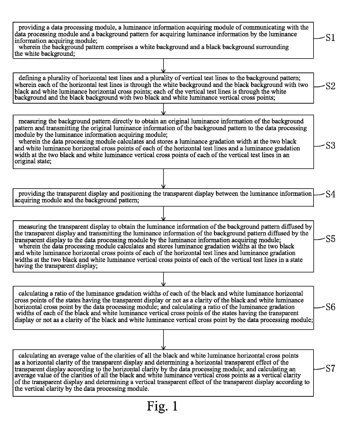
[0075]Please refer to FIG. 1. The present invention first provides a method of measuring a transparent effect of a transparent display, comprising steps of:

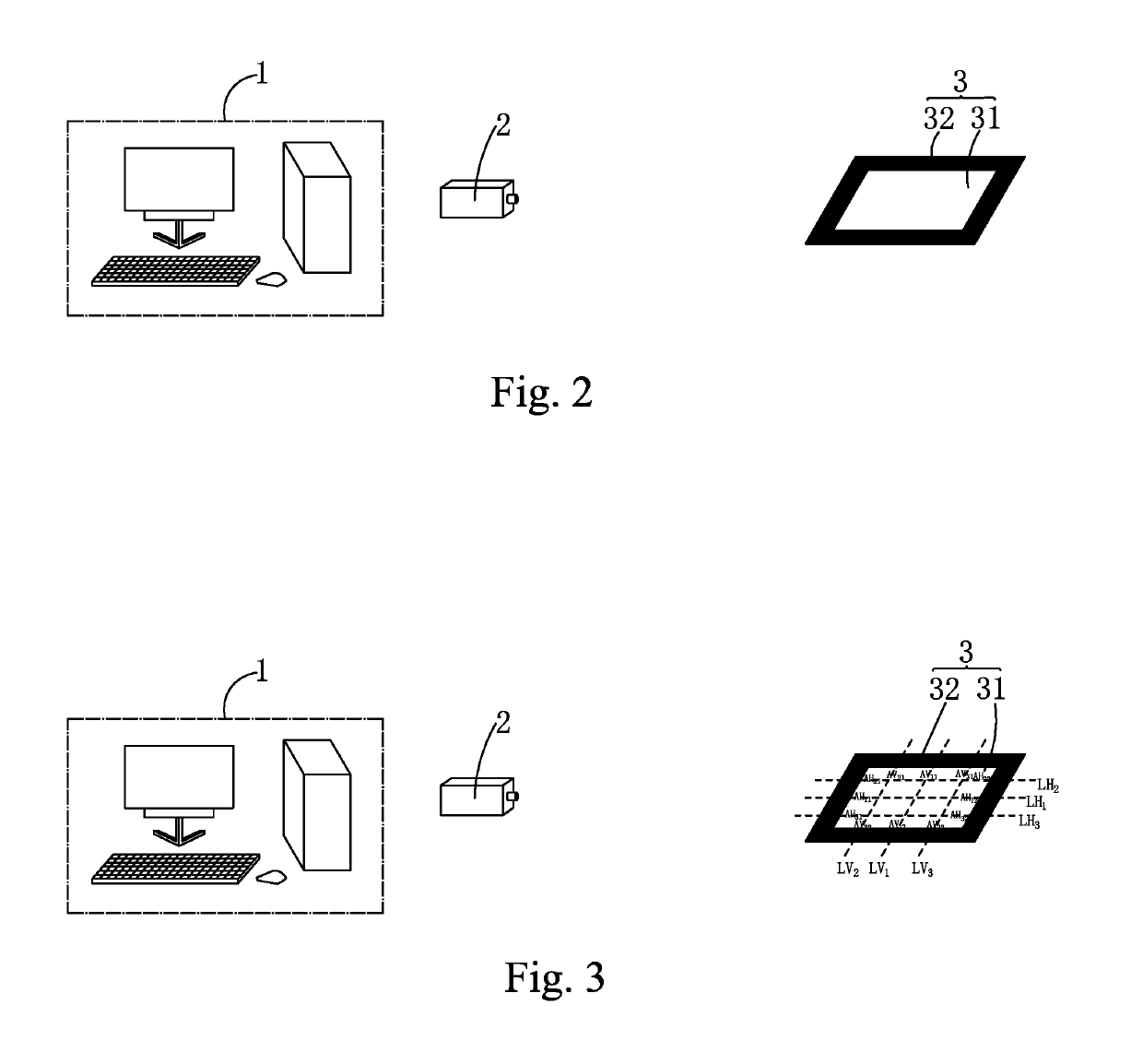
[0076]Step S1, as shown in FIG. 2, providing a data processing module 1, a luminance information acquiring module 2 of communicating with the data processing module 1 and a background pattern 3 for acquiring luminance information by the luminance information acquiring module 2.

[0077]Specifically, the data processing module 1 is preferably a computer.

[0078]The luminance information acquiring module 2 is preferably a luminance meter or an image sensor.

[0079]The background pattern 3 comprises a white background 31 and a black background 32 surrounding the white background 31.

[0080]Step S2, as shown in FIG. 3, setting i and n t...


PUM

PropertyMeasurementUnit
transparentaaaaaaaaaa
luminanceaaaaaaaaaa

Abstract

The luminance information acquiring module acquires luminance information of the background pattern in states having transparent display or not. The data processing module calculates the luminance gradation width of each black and white luminance horizontal cross point and each black and white luminance vertical cross point on the background pattern in states having transparent display or not and then, calculates a ratio of the luminance gradation width of each black and white luminance horizontal cross point and each black and white luminance vertical cross point in states having transparent display or not as clarities of the black and white luminance horizontal cross point and the black and white luminance vertical cross point and finally, calculates average values of the clarities of all the black and white luminance horizontal cross points and all the black and white luminance vertical cross points as a horizontal clarity and a vertical clarity.

Description

FIELD OF THE INVENTION[0001]The present invention relates to a display measuring field, and more particularly to a method and a system of measuring a transparent effect of a transparent display.BACKGROUND OF THE INVENTION[0002]In the display field, Liquid Crystal Display (LCD), Organic Light Emitting Diode (OLED) and other panel display devices have been gradually replaced the Cathode Ray Tube (CRT) displays. The LCD (Liquid Crystal Display) possesses many advantages of being ultra thin, power saved and radiation free. It has been widely utilized. The Organic Light Emitting Display (OLED) display possesses many outstanding properties of self-illumination, low driving voltage, high luminescence efficiency, short response time, high clarity and contrast, near 180° view angle, wide range of working temperature, applicability of flexible display and large scale full color display and therefore is considered as a dream display. The OLED can be categorized as Passive matrix OLED (PMOLED) ...

Claims


Application Information

Patent Timeline
Patent Type & Authority Patents(United States)
IPC IPC(8): G09G3/00G02F1/13G06F3/03G09G3/3225G09G3/36
CPCG02F1/1309G09G3/006G06F3/0325G09G2360/16G09G3/3648G09G3/3225G01M11/02
Inventor WANG, LIMIN
Owner SHENZHEN CHINA STAR OPTOELECTRONICS SEMICON DISPLAY TECH CO LTD
Why Eureka
Try Eureka