
Display apparatus

a technology of display apparatus and display data, applied in the direction of instruments, static indicating devices, etc., can solve the problems of inability to effectively measure the pixel charging rate by a general voltage measuring apparatus, the display data may not be correctly written in the pixels, and the pixels cannot display the correct image. achieve the effect of easily and effectively measuring the pixel charging ra

Active Publication Date: 2019-07-02
E INK HLDG INC
View PDF19 Cites 0 Cited by
  • Summary
  • Abstract
  • Description
  • Claims
  • Application Information

AI Technical Summary

Benefits of technology

[0005]The invention provides a display apparatus that measures a pixel charging rate easily and effectively.
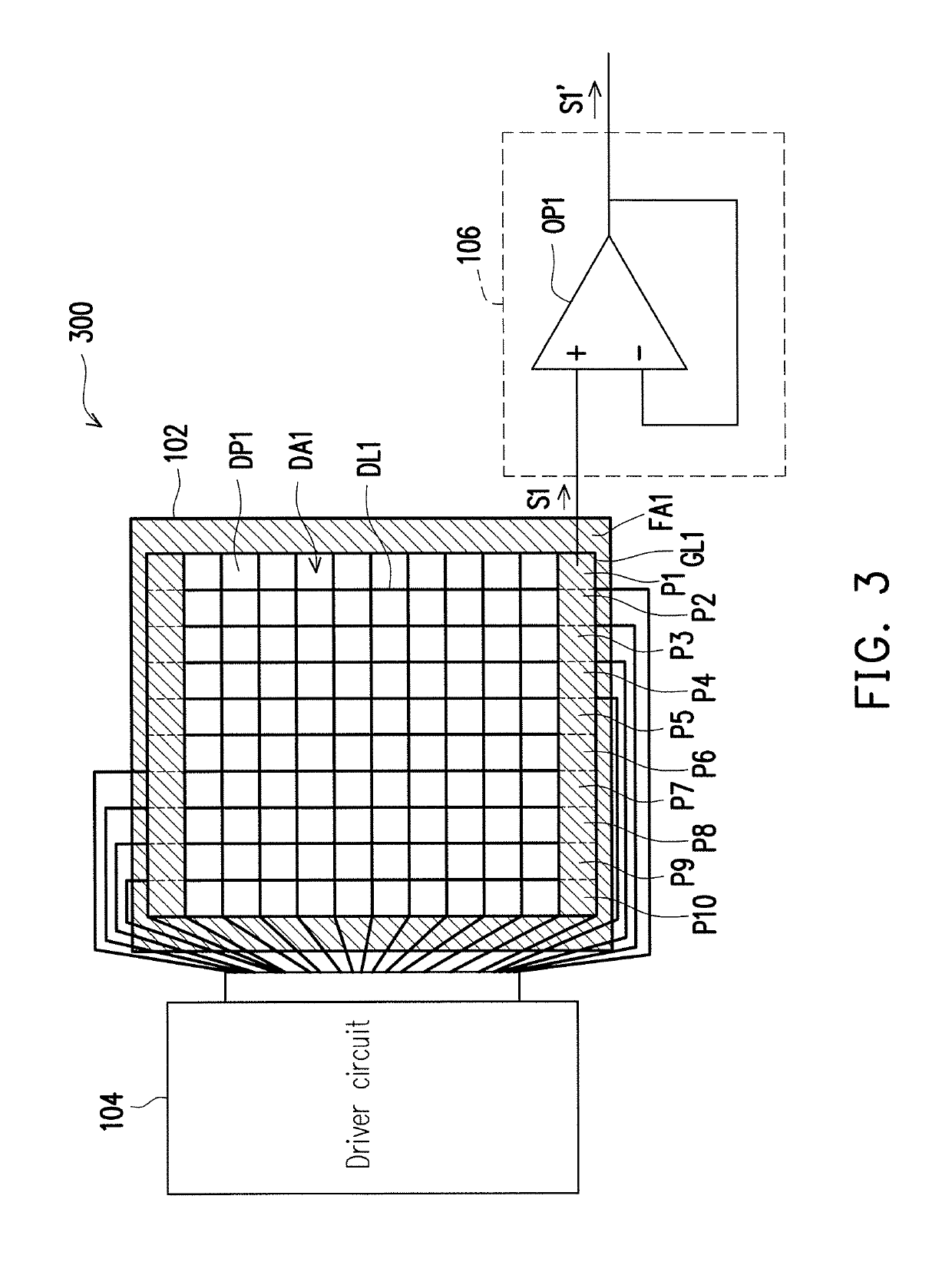
[0016]Based on the above, in the exemplary embodiments of the invention, the dummy pixels in the non-display region are connected to one another, and the gate driving voltages and the test data voltage are provided to the dummy pixels connected to one another, such that the dummy pixels connected to one another provide the charging rate test signal providing a sufficiently large voltage value in response to the test data voltage. Thereby, measurement of the pixel charging rate is performed easily and effectively.

Problems solved by technology

If the charging rate of the pixels is too slow, the display data may not be correctly written in the pixels.
That is, the pixels are unable to display the correct image.
When the pixels are driven, the individual pixels have small voltage variation, which cannot be effectively measured by a general voltage measuring apparatus.
Thus, how to perform measurement of the pixel charging rate has become an issue.

Method used


Image

  • Display apparatus
  • Display apparatus
  • Display apparatus

Examples


Embodiment Construction

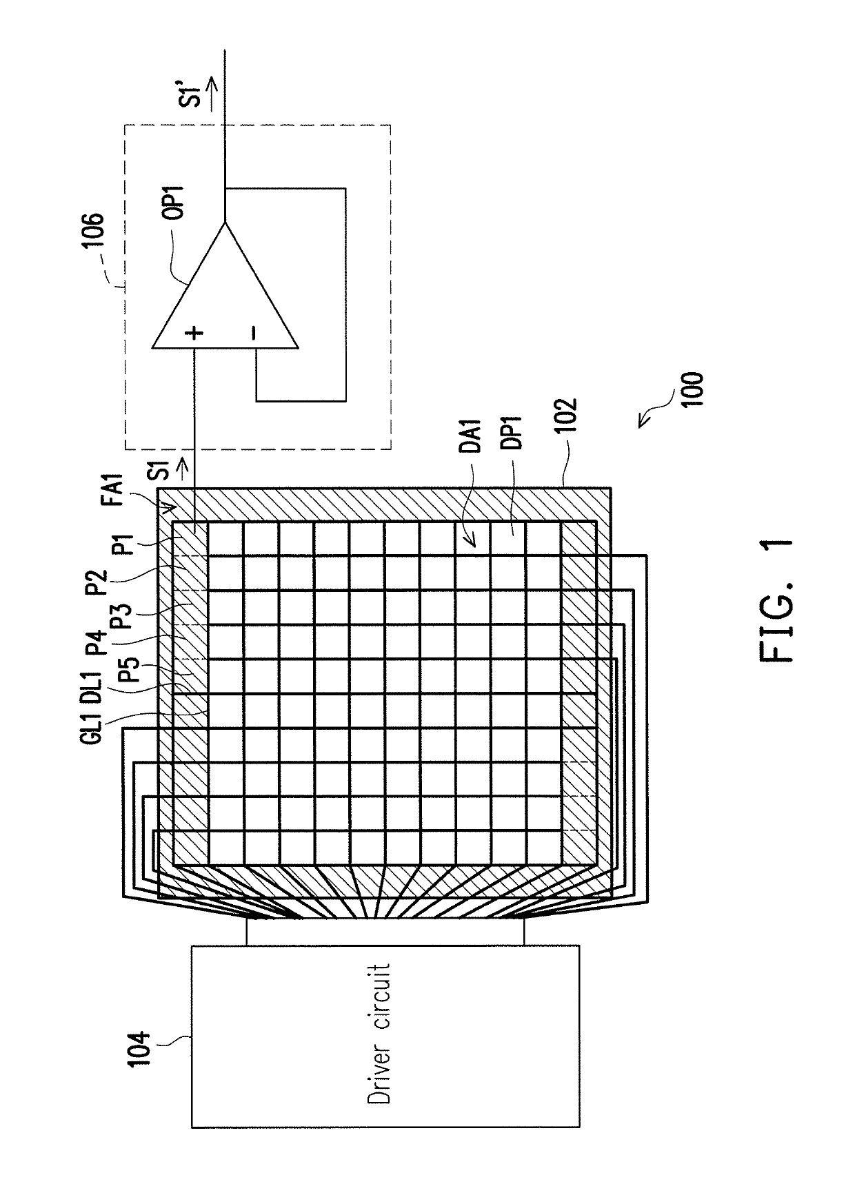
[0023]FIG. 1 shows a schematic view of a display apparatus according to an embodiment of the invention. Referring to FIG. 1, a display apparatus 100 includes a display panel 102 and a driver circuit 104. The driver circuit 104 is coupled to the display panel 102. The display panel 102 is a hard display panel or a soft display panel, e.g., an a-Si TFT display panel, an OTFT display panel, an OLED display panel, and so on. The display panel 102 includes a plurality of gate lines GL1, a plurality of data lines DL1, a plurality of dummy pixels (for example, P1 to P5) and a plurality of display pixels DP1. The display panel 102 has a display region DA1 and a non-display region FA1 (the hatched region as shown in FIG. 1). The dummy pixels are located in the non-display region FA1 and are disposed respectively at intersections of the corresponding gate lines GL1 and the data lines DL1 to be connected to the corresponding gate lines GL1 and the corresponding data lines DL1. To keep the draw...


PUM


Abstract

A display apparatus including a display panel and a driver circuit is provided. The display panel includes a display region and a non-display region. The non-display region includes a plurality of dummy pixels connected to one another. The driver circuit provides gate driving voltages and a test data voltage, so as to make the dummy pixels connected to one another generate a charging rate test signal in response to the test data voltage.

Description

CROSS-REFERENCE TO RELATED APPLICATION[0001]This application claims the priority benefit of China application serial no. 201710025908.1, filed on Jan. 13, 2017. The entirety of the above-mentioned patent application is hereby incorporated by reference herein and made a part of this specification.BACKGROUND OF THE INVENTIONField of the Invention[0002]The invention relates to a display apparatus and particularly relates to a display apparatus for measuring a voltage charging rate of pixels.Description of Related Art[0003]An image of a general thin display is formed by displaying a plurality of pixels in different gray levels. In general, a gate driving signal on a gate line determines the time that the pixels receives data voltages, and a data line transmits the data voltages to the pixels so as to charge the pixels to show gray levels corresponding to the display data. Therefore, the charging rate of the pixels closely relates to the display quality of the display. If the charging ra...

Claims


Application Information

Patent Timeline
Patent Type & Authority Patents(United States)
IPC IPC(8): G09G3/00G09G3/20
CPCG09G3/006G09G3/20G09G3/2018G09G2320/0295G09G2300/08G09G2310/0264G09G2320/029G09G2300/0413
Inventor KUO, WEN-YUHUANG, GUAN-RUHUANG, PEI-LINCHEN, WEI-TSUNG
Owner E INK HLDG INC
Learn More