Pyrotechnic isolator

a technology of isolating punch and pyrotechnics, which is applied in the direction of explosion-operated switches, high-tension/heavy-dress switches, and conductor severing switches, etc., can solve the problems of constant heating of igniters and ignition lines, high energy requirements of electrical systems, and malfunctions or damage of sensitive devices, so as to prevent elastic rebounding of isolating punches, reduce the effect of severing power and reducing the amount of s

Active Publication Date: 2019-09-17
HIRTENBERGER AUTOMOTIVE SAFETY GMBH
View PDF26 Cites 5 Cited by
  • Summary
  • Abstract
  • Description
  • Claims
  • Application Information

AI Technical Summary

Benefits of technology

[0013]It is the object of the present invention to provide an economical circuit breaker that enables the disconnection of a circuit breaker with currents of up to 8 kA and voltages of up to 500 V and beyond.
[0025]The isolating medium can thus also continue moving when the isolating punch has already been stopped; this movement of the isolating medium has the effect that fresh, cool isolating medium always reaches the electric arc that is favorable for extinguishing it.

Problems solved by technology

These electromechanical systems have the drawback that they require to operate a high level of energy that must be made available by power semiconductors and cabling having the appropriate cross section.
The effect of mechanical shocks as a result of drive operation can cause tiny interruptions in the power supply that can lead to malfunctions or damage in sensitive devices.
The main problem with this type of construction is that the igniter and ignition line are constantly being heated by the flow of current in the conductor and age.
Switches having this construction are limited in their disconnecting capacity both in terms of the voltage and the amperage (at about 1 kA).
A thermoplastic would also have little durability in the presence of a possible electric arc.
The construction is elaborate and therefore cost- and space-intensive.
It is disadvantageous that this construction only works with conductors that have been substantially pre-weakened, as described for example in DE 102010011150 [U.S. Pat. No. 9,425,010], to be disconnected.

Method used


Image

  • Pyrotechnic isolator

Examples


Embodiment Construction

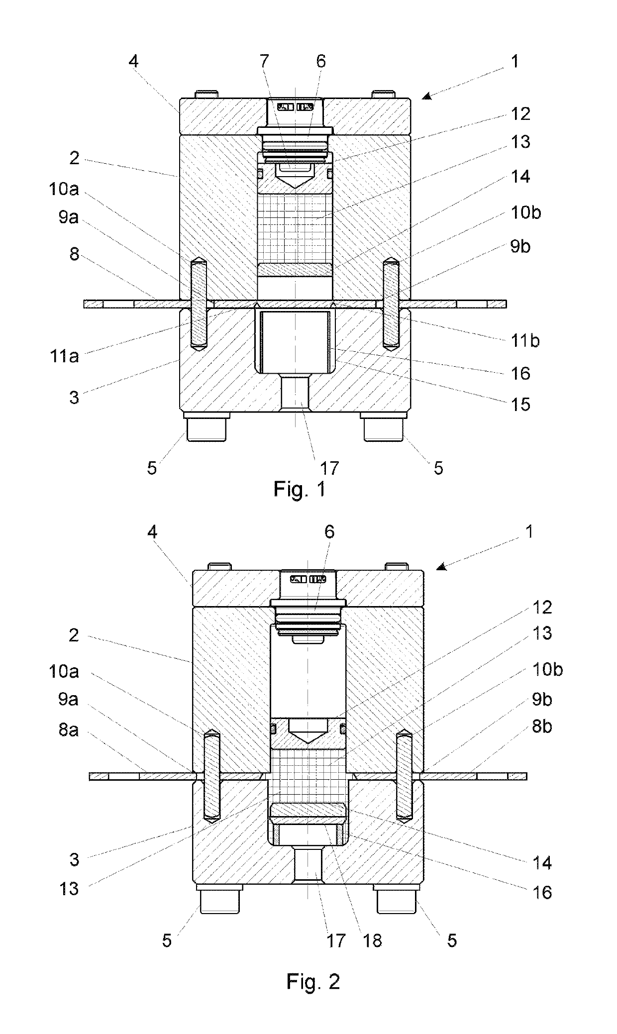
[0012]The current state of the art does not satisfactorily meet the challenge of reliably disconnecting intense currents at high voltages while simultaneously keeping system costs economical.

[0013]It is the object of the present invention to provide an economical circuit breaker that enables the disconnection of a circuit breaker with currents of up to 8 kA and voltages of up to 500 V and beyond.

[0014]According to the invention, this object is achieved by a circuit breaker of the type mentioned above in that an extinguishing medium for suppressing or extinguishing the electric arc occurring during disconnection is provided between the isolating punch and the ignition unit so that it is pressurized upon ignition and drives the isolating punch.

[0015]By virtue of the isolating punch, a high force for disconnecting the conductor is thus made available as usual so that the conductor need only be weakened moderately. Nevertheless, after the isolating punch has passed through the conductor...


PUM


Abstract

The pyrotechnic isolating apparatus (1) for isolating a conductor (8) using an isolating punch (14) has a housing, in which the isolating punch (14) is routed, and an ignition unit (6) for driving the isolating punch (14). According to the invention, a quenching means (13) for suppressing or quenching an arc is arranged between the isolating punch (14) and the ignition unit (6). Therefore, the quenching means (13) also transmits the drive force to the isolating punch (14). The isolating punch (14) can have at least one cutting edge, so that a printed circuit board (18) is stamped out of the conductor (8) and the conductor ends (8a, 8b) are at a large distance. The isolating punch (14) is preferably composed of electrically conductive material with a melting point of greater than 2000° C. It is advantageous when a thrust piston (12) is provided between the ignition unit (6) and the quenching means (13) in order to shield the hot combustion gases from the quenching means (13). In order to brake the isolating punch (14), a damping element (16) can be provided on the opposite side of the conductor (8). When the isolating punch is at a lateral distance from the housing at least in regions there, the quenching means (13) can continue to flow even after the isolating punch (14) is braked.

Description

CROSS REFERENCE TO RELATED APPLICATIONS[0001]This application is the US-national stage of PCT application PCT / AT2016 / 060085 filed 19 Oct. 2016 and claiming the priority of Austrian patent application A50889 / 2015 itself filed 19 Oct. 2015.FIELD[0002]The present invention relates to a pyrotechnic circuit breaker for disconnecting a conductor by means of an isolating punch, with the circuit breaker having a housing in which the isolating punch is movable and an ignition unit for driving the isolating punch.PRIOR ART[0003]In automobile safety, battery disconnection systems have the task of switching off certain circuits in a collision in order to minimize the risk of fire. Components that are not necessary for emergency operation are disconnected from the power supply in order to reduce the risk of a fire in the event of a short circuit.[0004]The first electrically operable battery disconnection systems consisted of available electromechanical components, as described, for the sake of e...

Claims


Application Information

Patent Timeline
Patent Type & Authority Patents(United States)
IPC IPC(8): H01H9/30H01H39/00H01H9/32
CPCH01H39/006H01H9/30H01H9/32H01H2039/008H01H33/92
Inventor WARENITS, PETERMUNOZ, LEYTON
Owner HIRTENBERGER AUTOMOTIVE SAFETY GMBH
Why Eureka
Try Eureka