Vehicle lighting system

a technology for vehicle lighting and lighting systems, applied in the direction of pedestrian/occupant safety arrangements, scene recognition, instruments, etc., can solve the problems of inability to give proper caution to the physical body, inability to detect the physical body exactly, and inability to accurately detect the physical body in the periphery of the vehicl

Active Publication Date: 2019-09-24
TOYOTA JIDOSHA KK
View PDF20 Cites 6 Cited by
  • Summary
  • Abstract
  • Description
  • Claims
  • Application Information

AI Technical Summary

Benefits of technology

[0008]The present disclosure provides a vehicle lighting system that can properly give a caution by emitting light.
[0010]In the vehicle lighting system according to the aspect, a first light is emitted to the physical body detected by a detector using an electromagnetic wave. Thereby, the detection of the physical body by a camera using the image information is suitably performed. As a result, it is possible to exactly determine whether the physical body is the object, and to give a suitable caution with a second light.

Problems solved by technology

However, in a camera that performs capture using visible light, there could be a case that the physical body existing in the periphery of the vehicle cannot be exactly detected in a situation of a dark environment during night-time or the like.
As described above, when the detection of the physical body existing in the periphery of the vehicle is insufficient, there is a fear that a proper caution cannot be given to the physical body.
Specifically, when the attribute of the physical body cannot be discriminated, it is not possible to give a caution corresponding to the attribute of the physical body (for example, it is not possible to decide whether to give a caution intended for a pedestrian or give a caution intended for a vehicle), even when the existence of the physical body can be detected.
Further, it is not possible to properly determine whether the physical body is an object to which the caution needs to be given, and there could be a case that the light is emitted to a physical body that is not the object, or the light is not emitted to a physical body that is the object.

Method used


Image

  • Vehicle lighting system
  • Vehicle lighting system
  • Vehicle lighting system

Examples


first embodiment

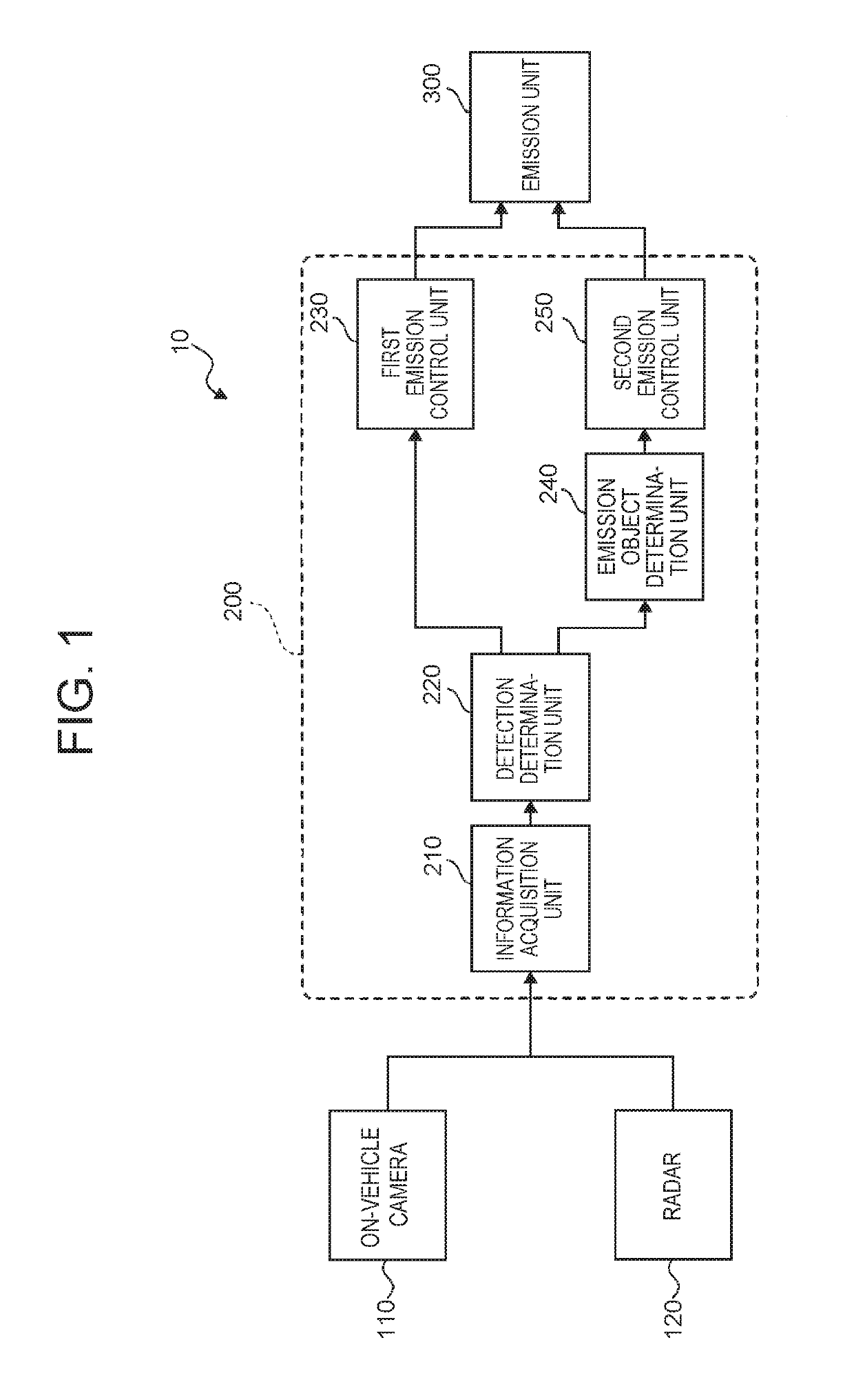
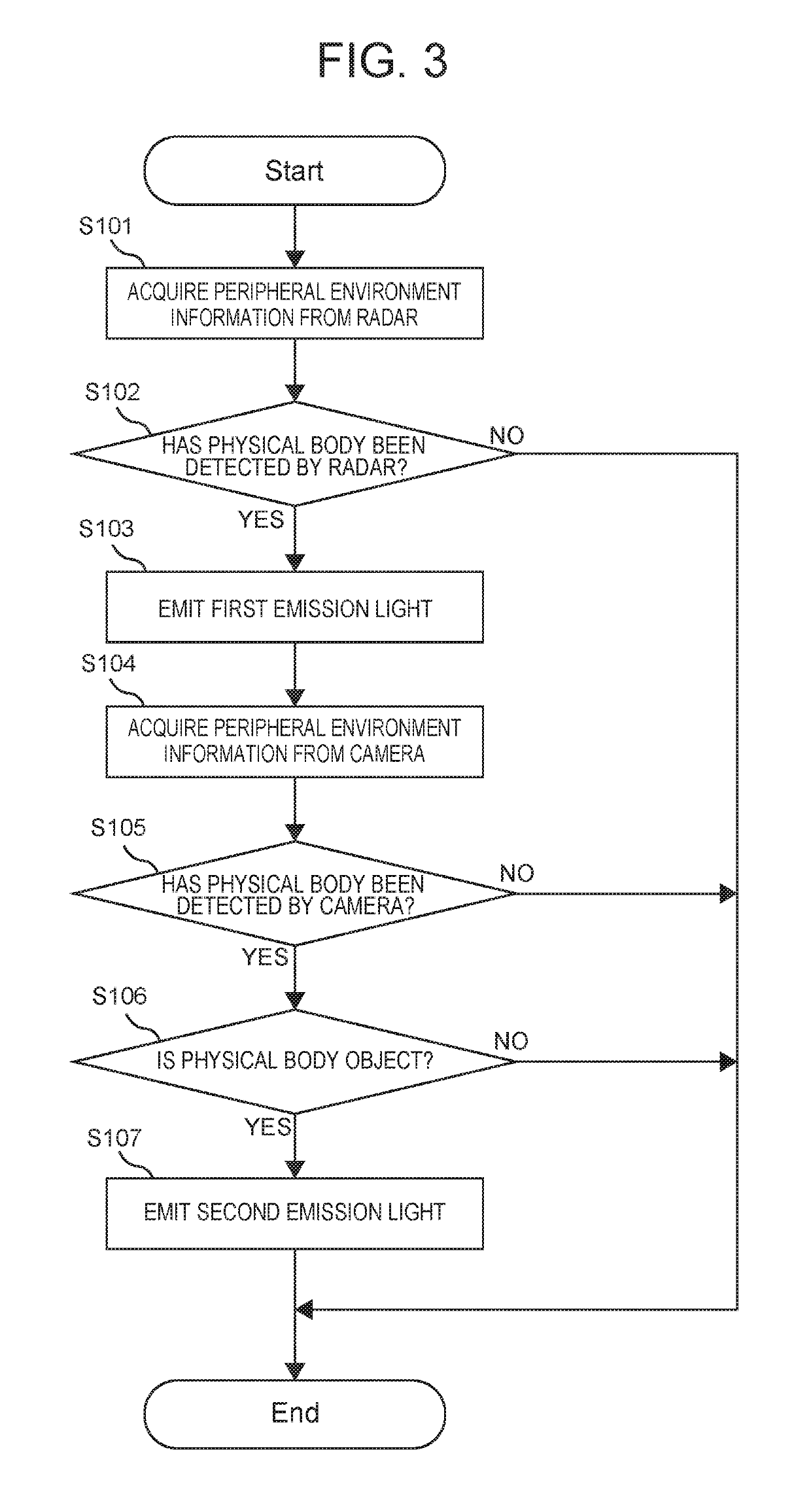
[0024]First, a vehicle lighting system according to the first embodiment will be described with reference to FIG. 1 to FIG. 8. In the following, a configuration of the vehicle lighting system, a possible problem at the time of the detection of a physical body by an on-vehicle camera, an operation of the vehicle lighting system, specific exemplary emissions, and technical effects to be obtained by the vehicle lighting system will be described in order.

[0025]

[0026]First, the configuration of the vehicle lighting system according to the first embodiment will be described with reference to FIG. 1. Here, FIG. 1 is a block diagram showing the configuration of the vehicle lighting system according to the first embodiment.

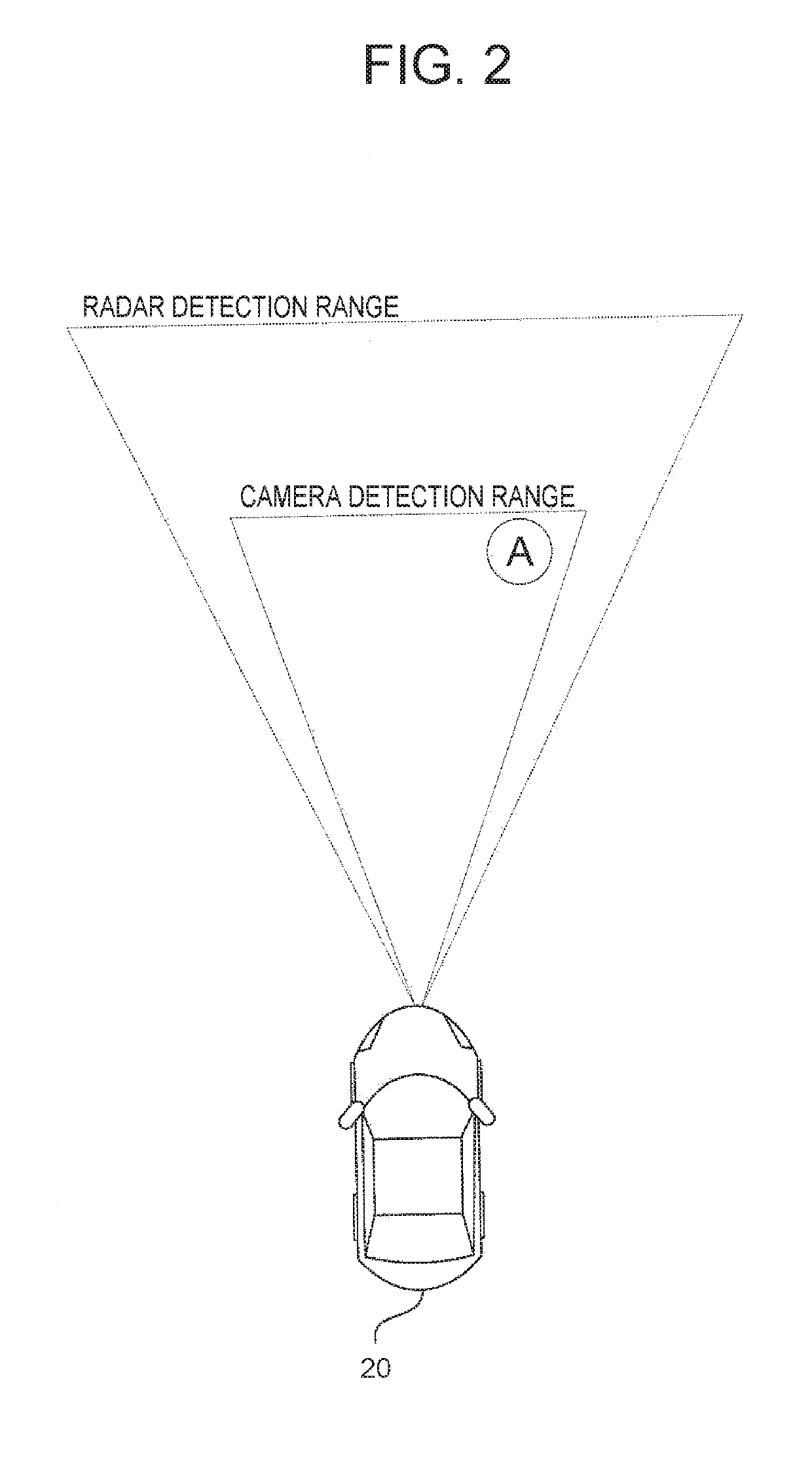
[0027]In FIG. 1, a vehicle lighting system 10 according to the embodiment is mounted in a vehicle such as an automobile, and is configured to be able to give a caution about the own vehicle by emitting light toward an object (for example, a pedestrian) to which the caution...

second embodiment

[0078]Next, a vehicle lighting system according to the second embodiment will be described with reference to FIG. 9 to FIG. 11. Here, the second embodiment is different from the already-described first embodiment, only in some parts of the configuration and operation, and is the same in many other parts. Therefore, hereinafter, the different parts from the first embodiment will be described in detail, and the description of the other repetitive parts will be omitted when appropriate.

[0079]

[0080]First, a configuration of the vehicle lighting system according to the second embodiment will be described with reference to FIG. 9. Here, FIG. 9 is a block diagram showing the configuration of the vehicle lighting system according to the second embodiment.

[0081]In FIG. 9, a vehicle lighting system 10b according to the second embodiment is configured to include an external illuminance sensor 130, in addition to the configuration (see FIG. 1) of the first embodiment. Further, the vehicle light...


PUM


Abstract

A vehicle lighting system includes: a lighting device that emits a first light and a second light to a periphery of an own vehicle, the second light having a higher directivity than the first light; a camera to acquire image information; a detector to emit an electromagnetic wave and acquire a reflection wave; and an electronic control unit configured to detect a physical body using the image information, detect the physical body using information of the reflection wave, control the lighting device such that the first light is emitted to the physical body detected by the reflection wave, determine whether the physical body detected using the image information in a state where the first light is being emitted is an target object, and control the lighting device such that the lighting device emits the second light toward a predetermined range around the target object.

Description

INCORPORATION BY REFERENCE[0001]The disclosure of Japanese Patent Application No. 2016-048889 filed on Mar. 11, 2016 including the specification, drawings and abstract is incorporated herein by reference in its entirety.BACKGROUND[0002]1. Technical Field[0003]The disclosure relates to the technical field of a vehicle lighting system.[0004]2. Description of Related Art[0005]As this kind of system, there is known a technology of giving a caution by emitting light toward an object existing in the periphery of the own vehicle. Japanese Patent Application Publication No. 2011-084106 (JP 2011-084106 A) proposes a technology of emitting light toward an object detected by an on-vehicle camera, using a light device whose emission direction can be controlled in a front-back direction and a right-left direction, and thereby making the object recognize the existence of the own vehicle.SUMMARY[0006]In the technology described in JP 2011-084106 A, at a stage prior to the light emission, the camer...

Claims


Application Information

Patent Timeline
Patent Type & Authority Patents(United States)
IPC IPC(8): H04N7/18B60Q1/28B60Q1/46G01S13/86G01S13/93B60Q9/00B60K35/00B60Q5/00B60Q1/00G06K9/00B60Q1/08G08G1/16B60R21/0134G01S13/931G06V10/143
CPCB60Q1/46B60Q9/004G08G1/166B60Q5/006B60Q1/085G06K9/00805B60Q1/28B60Q9/006G01S13/867G01S13/931B60K35/00B60Q9/005B60Q1/0023G06K9/00369B60R21/0134B60K2370/29B60R2300/301B60K2370/188B60K2370/797B60K2370/20B60K2370/21B60K2370/334B60Q2300/05B60R2300/8033B60R2300/8093B60Q2300/45B60W2420/403B60Q2300/33B60R2300/307B60W2550/10B60W2420/42B60W2420/52B60Q2400/50B60Q1/26B60K2370/191B60K2370/178B60W2050/143G06V20/58G06V10/143B60W2554/00G06V40/103
Inventor NAGATA, SHINICHIKAWAMATA, SHINYAFUJITA, KAZUYUKISATO, MINAMI
Owner TOYOTA JIDOSHA KK
Why Eureka
Try Eureka