
Connector device with connector and assembly method

a technology of connectors and connectors, applied in the field of connectors, can solve the problems of high effort (machinery, specific designed equipment) needed to integrate the assembly into an automated production, and achieve the effects of reliable electrical connection, reduced effort for mounting the pcb and

Active Publication Date: 2019-09-24
BRAUN GMBH
View PDF17 Cites 0 Cited by
  • Summary
  • Abstract
  • Description
  • Claims
  • Application Information

AI Technical Summary

Benefits of technology

[0005]It is accordingly one object of the present invention to provide an improved connector suitable for different types of devices with the connector providing a reliable electrical connection to the PCB while reducing the effort for mounting the PCB and the connector.
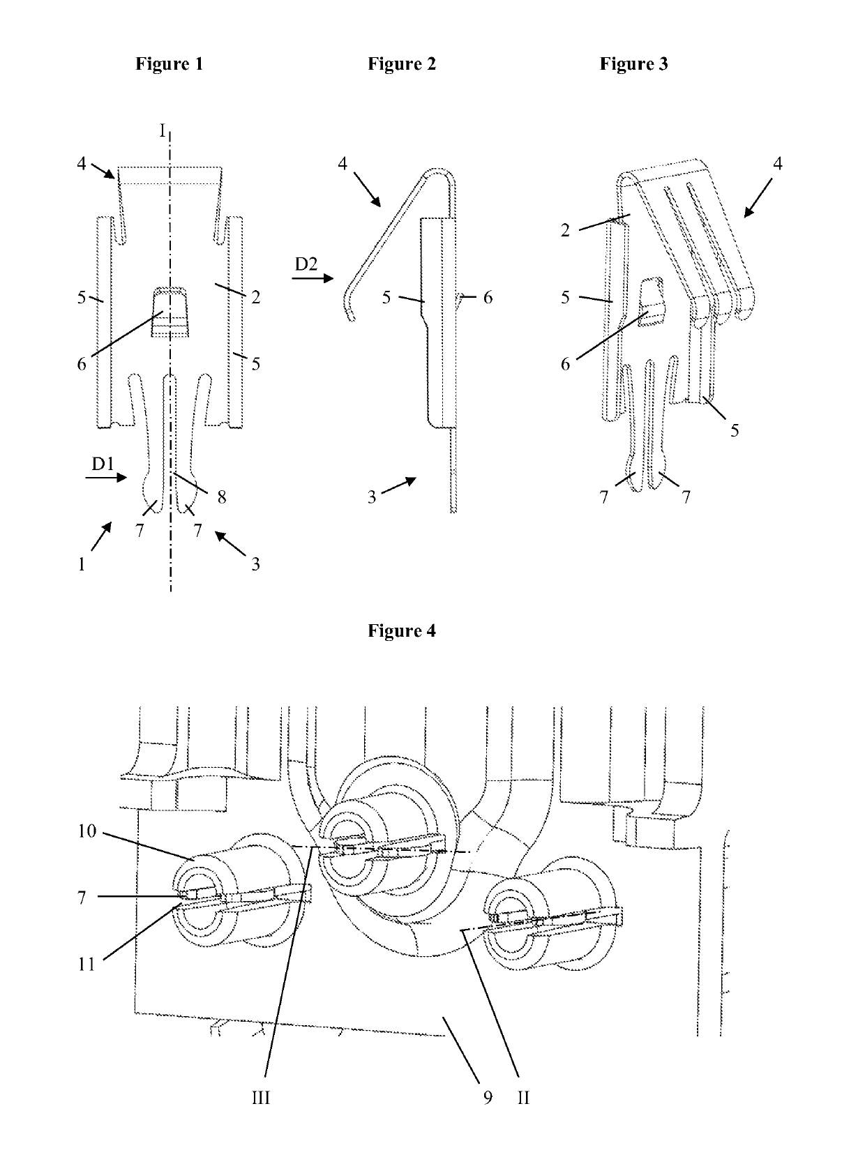
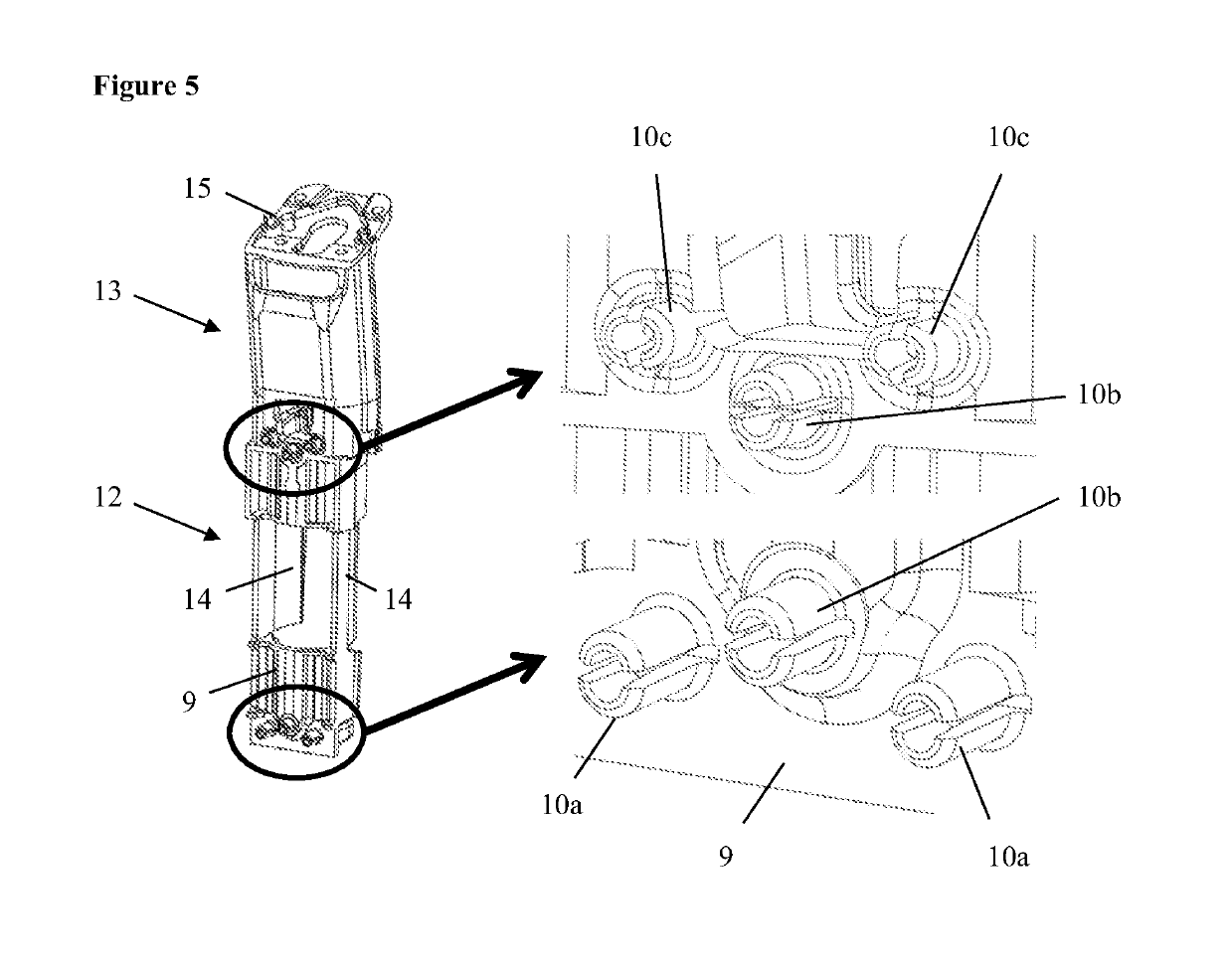
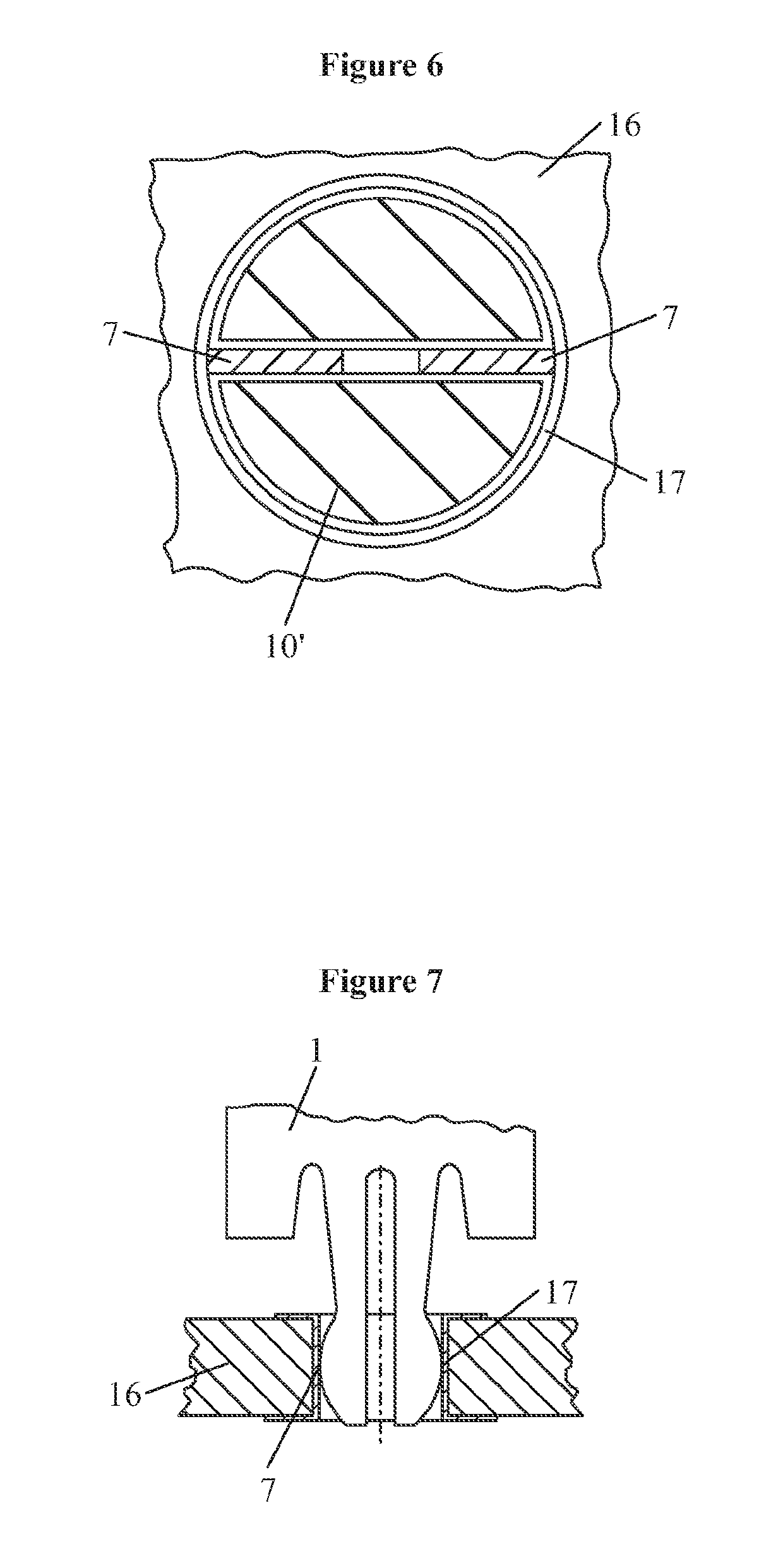
[0008]The invention proposes a beneficial way to connect an electronic component part, like a battery or a DC-motor, with a PCB which is suitable for an automated assembly of the e.g. battery to the PCB. The design of the contact clip of the connector increases the reliability of the manufacturing process due to a simplified assembly operation of the battery and / or the battery holder to the PCB. The assembly of the electromechanical components onto the PCB becomes a pure mechanical standard-like assembly process without the need to combine typical PCB-handling operations (like soldering) with typical mechanical assembly operations (defined movements, normally done via robots). In addition, the design results in reduced costs due to less parts and due to avoidance of soldering or other additional steps which are typically used to ensure a reliable and low-resistance electrical connection (simplified production process, lower production asset cost). Further, the contact clip provides a detachable connection, which is an advantage in maintenance and repair of the device but also in manufacturing, where pre-assembled units can be separated and at least partially reused in case of detection of a malfunction in a later production step (reversible assembly).

Problems solved by technology

However, the effort (machinery, specific designed equipment) needed to integrate the assembly into an automated production is high.

Method used


Image

  • Connector device with connector and assembly method
  • Connector device with connector and assembly method
  • Connector device with connector and assembly method

Examples


Embodiment Construction

[0019]The invention is disclosed in the following by way of exemplary embodiments realizing different features and aspects of the invention.

[0020]The contact clip of the connector may be designed such that the substrate and the first terminal extend at least substantially in a common plane along the longitudinal axis. As an alternative, the first terminal may be arranged in a bent configuration with respect to the substrate. The first terminal may be designed such that the longitudinal slot, in its unstressed condition, has a constant width and is open toward the respective free end of the first terminal. The outwardly directed outer edge of the contact tongues may be slightly convex. As an alternative, the outwardly directed outer edge of the contact tongues may comprise a section having an increased width.

[0021]The second terminal may be formed by folding a portion of the substrate onto the remaining portion of the substrate such that the second terminal and the remaining portion ...


PUM


Abstract

A connector is disclosed comprising at least one contact clip. The contact clip comprises an electrically conductive substrate having a longitudinal axis, a first terminal located at a first end of the substrate, wherein the first terminal comprises at least two contact tongues between which a longitudinal slot is formed, which contact tongues are elastically deformable with respect to each other in a first direction which is perpendicular to the longitudinal axis, and a second terminal located at a second end of the substrate. The connector may further comprise a chassis and a PCB. In addition, a device comprising an energy consumer, an electrical energy source, a PCB and at least one connector is disclosed.

Description

FIELD OF THE INVENTION[0001]The invention relates to a connector and a device comprising such a connector. The device may be a household device or a body treatment device, for example an electric toothbrush, an electric shaver, an electric epilator or the like. The connector may comprise at least one contact clip having an electrically conductive substrate with a longitudinal axis, a first terminal located at the first end of the substrate and a second terminal located at a second end of the substrate. The connector may further comprise a chassis and / or a PCB (printed circuit board). Further, the invention relates to a method for assembling a device comprising a connector.BACKGROUND OF THE INVENTION[0002]There are many different options to connect electromechanical components on a PCB. A very common and broadly used version is to connect via electrical wires, which can be soldered to the PCB and the battery. This is the typical solution for a manual assembly in manufacturing. There ...

Claims


Application Information

Patent Timeline
Patent Type & Authority Patents(United States)
IPC IPC(8): H01R4/26H01R12/58A61C17/16H01R13/432H01R13/05H01R12/70H01R13/11H01R4/245H01R4/48H01R43/16H01R12/71H01R13/20H01R13/24H01R13/26
CPCH01R13/432A61C17/16H01R13/112H01R4/245H01R12/7076H01R12/585H01R4/48H01R13/055H01R12/7023H01R43/16H01R13/052H01R13/20H01R13/2442H01R13/26H01R12/7029H01R12/714
Inventor ERNDT, ANDREASSTEGHAUS, MICHAELLANGSDORF, JAN CHRISTIANKLEMM, TORSTEN
Owner BRAUN GMBH
Learn More