Imaging lens
a technology of imaging lens and f-value, applied in the field of imaging lens, can solve the problems of aberration correction, aberration correction, and the recent requirement for wide field of view not being satisfied, and achieve the effect of wide field of view, low f value and high resolution
- Summary
- Abstract
- Description
- Claims
- Application Information
AI Technical Summary
Benefits of technology
Problems solved by technology
Method used
Image

Examples
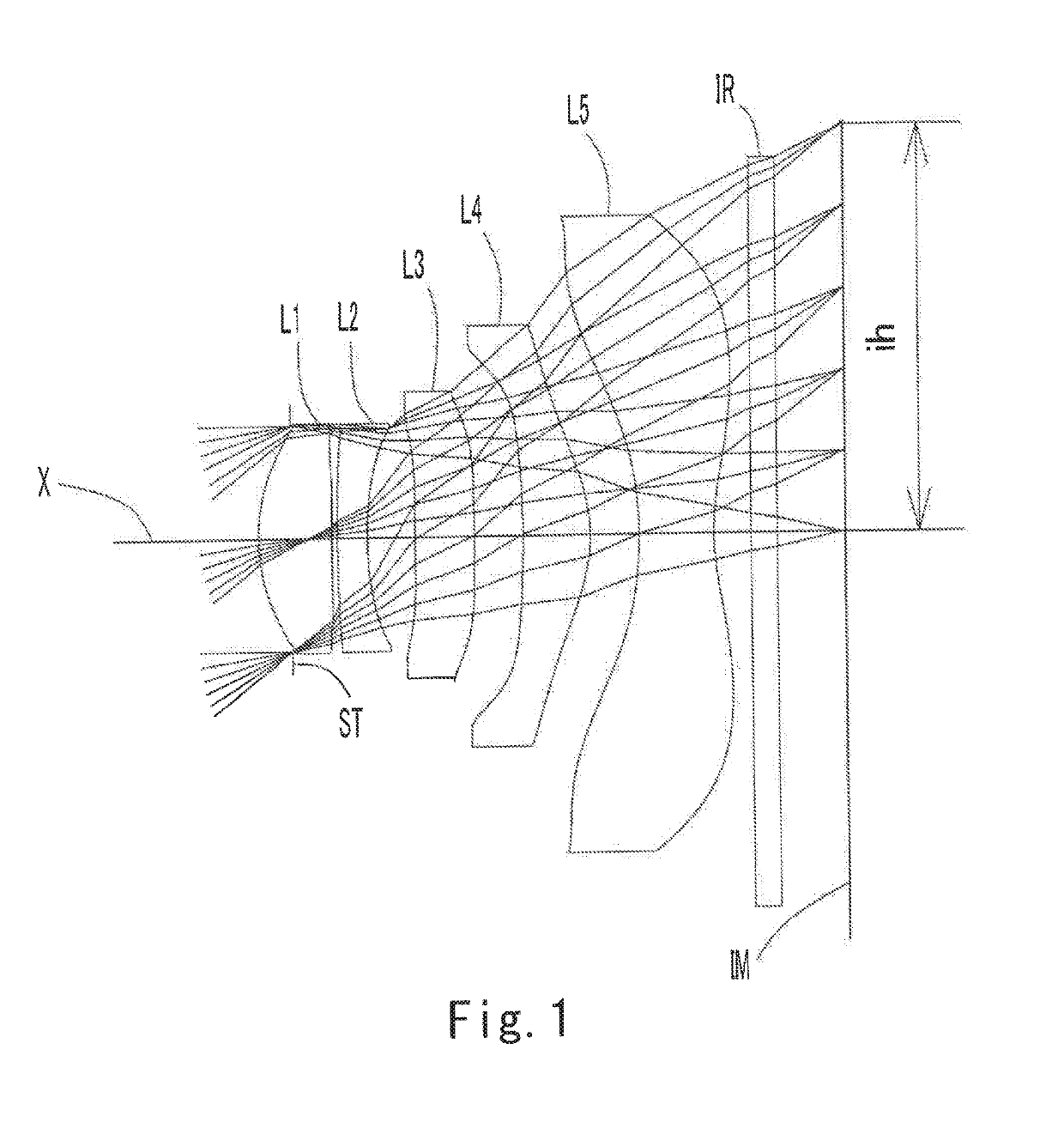
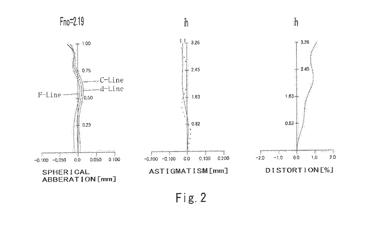
example 1
[0113]The basic lens data is shown below in Table 1.
[0114]
TABLE 1Numerical Data Example 1Unit mmf = 4.00ih = 3.26Fno = 2.19TLA = 4.58ω (°) = 38.8Surface DataSurfaceCurvatureSurfaceRefractiveAbbeNumber iRadius rDistance dindex NdNumber νd(Object)InfinityInfinity 1 (Stop)Infinity−0.25900 2*1.517620.585141.54455.57 3*24.687940.04131 4*10.852170.241371.65021.54 5*2.791270.38567 6*60.638990.467451.53556.16 7*197.161400.38290 8*−6.694440.520881.53556.16 9*−1.272670.3862510*−3.119640.594461.53556.1611*1.923540.5000012Infinity0.210001.51764.2013Infinity0.33339Image PlaneInfinityConstituent Lens DataLensStart SurfaceFocal Length122.9524−5.8536163.61482.84510−2.14Aspheric Surface DataSecond SurfaceThird SurfaceFourth SurfaceFifth SurfaceSixth SurfaceSeventh Surfacek0.000000E+000.000000E+000.000000E+00−2.149730E+000.000000E+000.000000E+00A47.506331E−03−1.394127E−01−1.625579E−01−2.462439E−02−1.129055E−01−7.915829E−02A6−4.512954E−024.693264E−016.236078E−012.627730E−01−1.091413E−01−1.165505E−01A8...
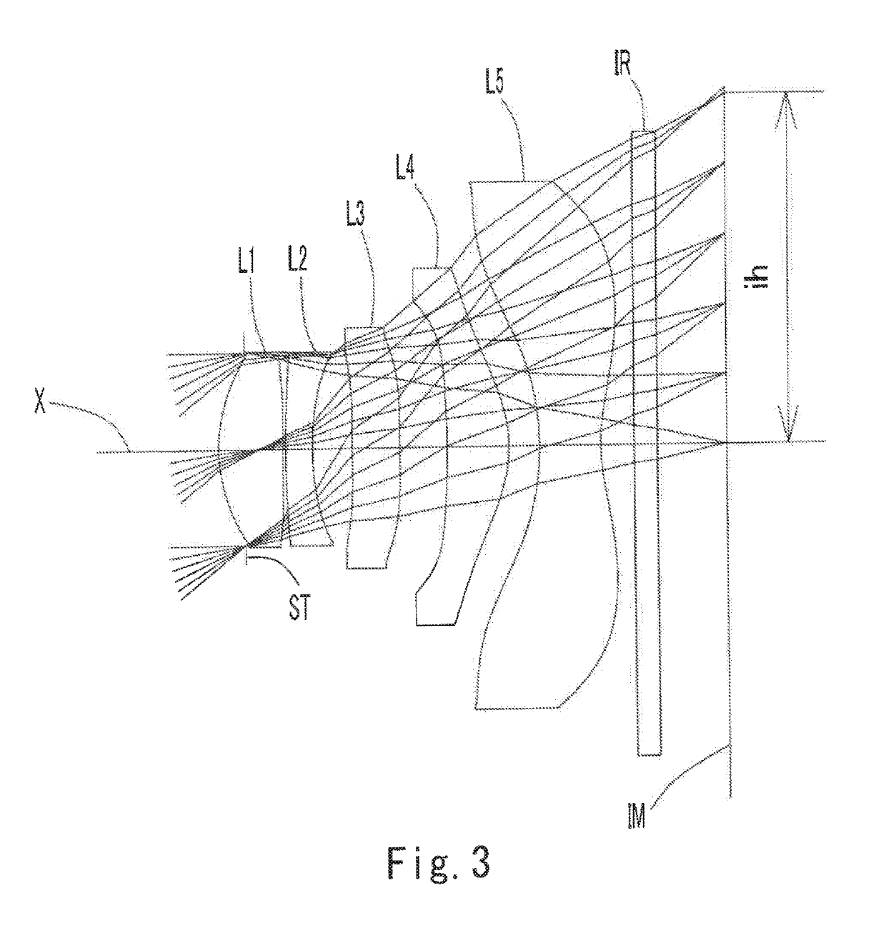
example 2
[0118]The basic lens data is shown below in Table 2.
[0119]
TABLE 2Numerical Data Example 2Unit mmf = 3.98ih = 3.26Fno = 2.23TLA = 4.58ω (°) = 38.9Surface DataSurfaceCurvatureSurfaceRefractiveAbbeNumber iRadius rDistance dindex NdNumber νd(Object)InfinityInfinity 1 (Stop)Infinity−0.24000 2*1.560560.583001.54455.57 3*26.801090.02300 4*8.736950.240001.65021.54 5*2.700270.36300 6*34.576510.441001.53555.66 7*−200.000000.44200 8*−8.770010.579001.53555.66 9*−1.148600.2810010*−2.534810.555001.53555.6611*1.756210.5000012Infinity0.210001.51764.2013Infinity0.43179Image PlaneInfinityConstituent Lens DataLensStart SurfaceFocal Length123.0224−6.103655.16482.41510−1.86Aspheric Surface DataSecond SurfaceThird SurfaceFourth SurfaceFifth SurfaceSixth SurfaceSeventh Surfacek0.000000E+000.000000E+000.000000E+00−5.068472E+000.000000E+000.000000E+00A47.240529E−03−1.563956E−01−1.597128E−012.636697E−03−1.339025E−01−1.028082E−01A6−6.336851E−026.364296E−017.156695E−012.015644E−01−1.440998E−02−7.327623E−02A81....
example 3
[0123]The basic lens data is shown below in Table 3.
[0124]
TABLE 3Numerical Data Example 3Unit mmf = 3.90ih = 3.26Fno = 2.25TLA = 4.58ω (°) = 39.4Surface DataSurfaceCurvatureSurfaceRefractiveAbbeNumber iRadius rDistance dIndex NdNumber νd(Object)InfinityInfinity 1 (Stop)Infinity−0.23500 2*1.524600.544001.54455.86 3*5.485100.04000 4*3.434000.240001.65021.54 5*2.136000.33400 6*10.767600.457001.53555.66 7*−200.000000.42400 8*−4.724000.597001.53555.66 9*−1.170300.1660010*−7.727500.700001.53555.6611*1.345700.5000012Infinity0.210001.51764.2013Infinity0.43653Image PlaneInfinityConstituent Lens DataLensStart SurfaceFocal Length123.7024−9.373619.12482.75510−2.09Aspheric Surface DataSecond SurfaceThird SurfaceFourth SurfaceFifth SurfaceSixth SurfaceSeventh Surfacek0.000000E+000.000000E+000.000000E+000.000000E+000.000000E+000.000000E+00A45.965788E−03−3.904468E−01−4.769130E−01−1.770315E−01−1.398482E−01−7.015717E−02A6−4.259745E−029.961244E−011.263878E+005.335076E−013.408424E−02−1.179972E−01A89.26...
PUM
 Abstract
Description
Claims
Application Information
 - R&D
- Intellectual Property
- Life Sciences
- Materials
- Tech Scout
- Unparalleled Data Quality
- Higher Quality Content
- 60% Fewer Hallucinations
Browse by: Latest US Patents, China's latest patents, Technical Efficacy Thesaurus, Application Domain, Technology Topic, Popular Technical Reports.
© 2025 PatSnap. All rights reserved.Legal|Privacy policy|Modern Slavery Act Transparency Statement|Sitemap|About US| Contact US: help@patsnap.com