
Control device for an asynchronous machine and method for operating an asynchronous machine

a control device and asynchronous machine technology, applied in the direction of torque ripple control, dynamo-electric converter control, instruments, etc., can solve the problems of the resonance of the machine and/or the components coupled thereto, and can adversely influence the emitted airborne noise of the electric driv

Active Publication Date: 2019-10-01
ROBERT BOSCH GMBH
View PDF9 Cites 0 Cited by
  • Summary
  • Abstract
  • Description
  • Claims
  • Application Information

AI Technical Summary

Benefits of technology

This approach effectively reduces airborne noise levels by preventing the excitation of resonance frequencies, maintaining efficiency and allowing dynamic control to mitigate noise issues without permanently deviating from optimal operating points.

Problems solved by technology

Resonances of the machine and / or the components coupled thereto, which can adversely influence the emitted airborne noise of the electric drive, occur in particular during the excitation of characteristic frequencies of the three-phase machine, for example, via the transfer of forces in the air gap between the stator and the rotor, or in the case of characteristic frequencies of the components which are flange-mounted on the drive shaft of the machine.

Method used


Image

  • Control device for an asynchronous machine and method for operating an asynchronous machine
  • Control device for an asynchronous machine and method for operating an asynchronous machine

Examples


Embodiment Construction

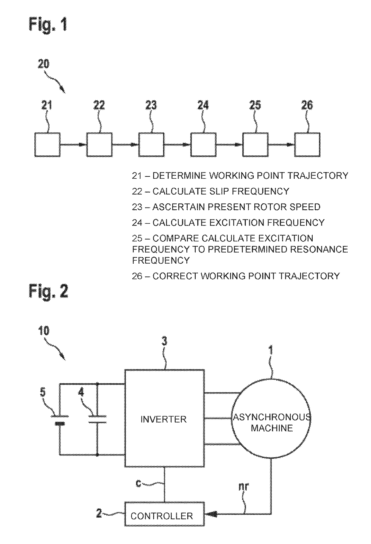
[0025]In the operation of an asynchronous machine as a motor, there is a difference between the speed ns of the stator and the actual speed nr, i.e., the actual speed of the rotor, and so the actual speed of the rotor is less than the speed of the stator. The difference is also referred to as slip—the corresponding slip frequency fs must therefore be added to the rotor frequency fr=p·nr, which is dependent on the number of pole pairs p of the asynchronous machine, in order to calculate the stator frequency fst:

fst=p·nr+fs

[0026]In the field-oriented closed-loop control of an asynchronous machine, in which the currents through the stator of the asynchronous machine are controlled according to a field-oriented coordinate system having a so-called longitudinal axis d and a quadrature axis q which extends orthogonal to the longitudinal axis, the d-axis therefore always lies in the direction of the space vector of the rotor flux. The space vector of the stator current is therefore compos...


PUM


Abstract

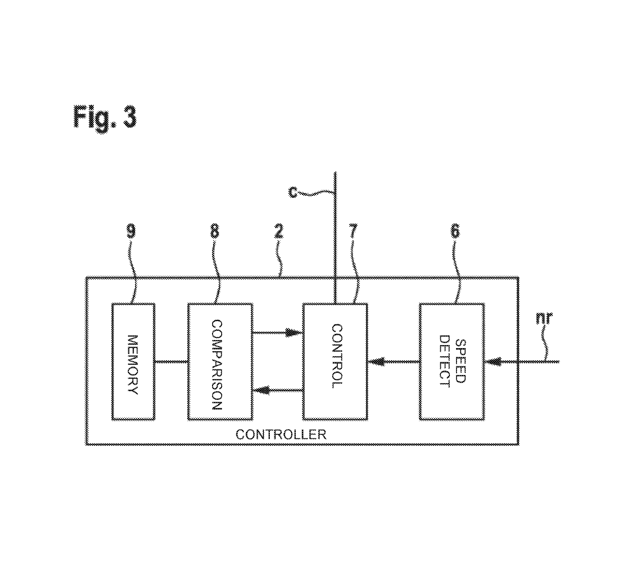
The invention relates to a method for operating an asynchronous machine comprising the steps: determining an operating point trajectory for the asynchronous machine for a plurality of desired torques of the asynchronous machine by calculating 2-tuples from longitudinal current values and cross current values in a synchronously rotating coordinate system of the asynchronous machine; calculating a slip frequency of the asynchronous machine for each of the 2-tuples calculated from longitudinal current values and cross current values; determining a current rotor speed of the asynchronous machine; calculating an excitation frequency of the asynchronous machine by summation of the calculated slip frequency and the current rotor speed weighted with the number of pole pairs of the asynchronous machine; and comparing the calculated excitation frequency of the asynchronous machine with at least one predetermined resonance frequency value of the asynchronous machine. The determined operating point trajectory is thereby corrected by changing the ratio between longitudinal current value and cross current value at a constant desired torque for each of the 2-tuples for which the calculated excitation frequency corresponds to the at least one resonance frequency value.

Description

BACKGROUND OF THE INVENTION[0001]The invention relates to a control device for an asynchronous machine and a method for operating an asynchronous machine.[0002]Document CH 477 124 A discloses an arrangement for controlling the slip frequency in an asynchronous machine.[0003]Electric drives having induction machines excite different frequencies in the three-phase machine depending on the operating point which has been determined on the basis of the speed and torque, which can cause solid-borne or airborne noise to be output and the ripple of the output torque to be influenced. Resonances of the machine and / or the components coupled thereto, which can adversely influence the emitted airborne noise of the electric drive, occur in particular during the excitation of characteristic frequencies of the three-phase machine, for example, via the transfer of forces in the air gap between the stator and the rotor, or in the case of characteristic frequencies of the components which are flange-...

Claims


Application Information

Patent Timeline
Patent Type & Authority Patents(United States)
IPC IPC(8): G01H3/00H02P1/00H02P23/08H02P6/10H02P27/06
CPCH02P1/00H02P23/08H02P27/06H02P21/05H02P2207/01H02P21/09
Inventor HENNEN, MARTIN
Owner ROBERT BOSCH GMBH
Learn More