
Pneumatic tire

a technology of pneumatic tires and tread patterns, which is applied in the direction of tyre tread bands/patterns, vehicle components, transportation and packaging, etc., can solve the problems of tire tread patterns that are generally subject to deterioration of road-hugging properties or deterioration of road-hugging properties and generation of uneven wear, etc., to achieve small radius of curvature, reduce uneven wear, and enhance rigidity

Active Publication Date: 2019-10-08
TOYO TIRE & RUBBER CO LTD
View PDF12 Cites 0 Cited by
  • Summary
  • Abstract
  • Description
  • Claims
  • Application Information

AI Technical Summary

Benefits of technology

The invention is a pneumatic tire with a tread portion that has multiple land portions divided by main grooves. The invention aims to reduce uneven wear and improve the tire's road-hugging property by balancing the rigidity of the land portions and reducing non-uniformity of ground contact pressure. This is achieved by designing the land portions with a smaller radius of curvature and a larger void ratio. As a result, a more rigid ground contact area is created, balancing the rigidity of the land portions and reducing uneven wear.

Problems solved by technology

A tire having such a tread pattern is generally subjected to deterioration of road-hugging property or generation of uneven wear due to non-uniform ground contact pressures of the plurality of land portions because the lateral grooves and the sipes are not provided evenly on the plurality of land portions.
However, in these documents, non-uniformity of the ground contact pressure caused by the lateral grooves and the sipes provided on the land portions when protruding the ground contact areas of a block is not considered, so that deterioration of the road-hugging property and generation of uneven wear may not be restricted.

Method used


Image

  • Pneumatic tire
  • Pneumatic tire
  • Pneumatic tire

Examples


example

[0041]Although the invention will be described below further specifically with Example, the invention is not limited to Example.

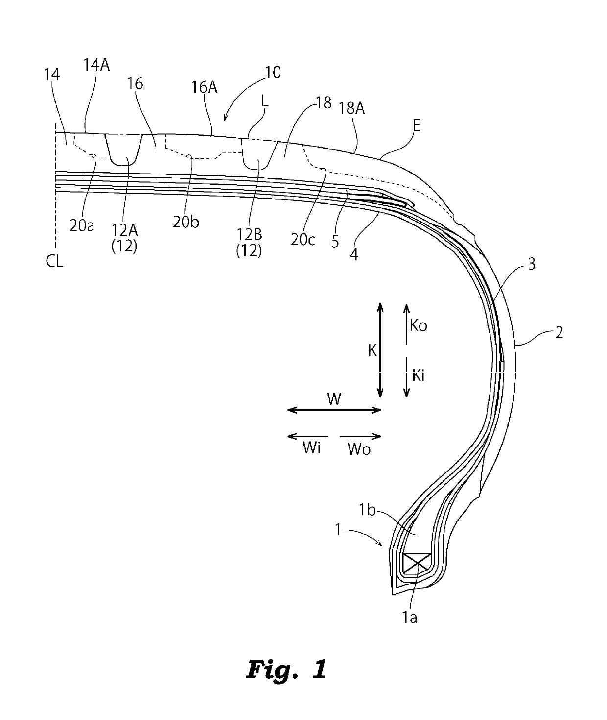
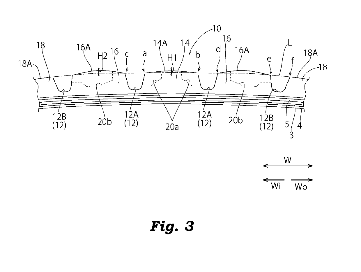
[0042]Pneumatic radial tires (215 / 55R17) of Example and Comparative Examples 1 and 2 are manufactured by way of trial. These tires of trial manufacture have the same basic tread pattern and the internal structure of the tire, and are manufactured by changing the cross-sectional shapes of the ground contact areas 14A and 16A of the center land portion 14 and the intermediate land portions 16 and 16.

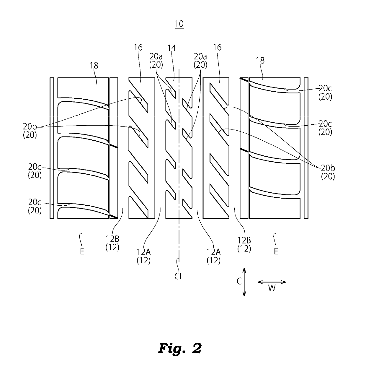
[0043]Specifically, configurations of Comparative Examples 1, 2 and Example have four main grooves illustrated in FIG. 2, and have the center land portion 14 having void ratio Xa of 15% and the intermediate land portions 16 and 16 having void ratio Xb of 18%. Comparative Example 1 is an example in which the protruding amounts of the center land portion 14 and the intermediate land portions 16 and 16 from the reference contour line L are the same, and cross-section...


PUM


Abstract

A pneumatic tire includes: a tread portion; three or more main grooves provided on the tread portion at intervals in a tire width direction so as to extend in a tire circumferential direction; and a plurality of land portions partitioned between the main grooves adjacent to each other in the tire width direction, wherein the plurality of land portions include: ground contact areas having an arc shape in cross section in the tire width direction; and depressed portions opening to the ground contact areas, and the land portion having a larger ratio of opening surface area a of the depressed portions opening in the area between the main grooves adjacent to each other in the tire width direction with respect to surface area A of the area (a / A) has an arc-shaped ground contact area with a cross section in the tire width direction having a smaller radius of curvature.

Description

BACKGROUND OF THE INVENTION[0001]Field of the Invention[0002]The present invention relates to a pneumatic tire.[0003]Description of the Related Art[0004]As a pneumatic tire, a tire having a tread pattern including a plurality of main grooves extending in a tire circumferential direction on a tread portion, and a plurality of land portions partitioned by the main grooves and provided with lateral grooves and sipes is known. A tire having such a tread pattern is generally subjected to deterioration of road-hugging property or generation of uneven wear due to non-uniform ground contact pressures of the plurality of land portions because the lateral grooves and the sipes are not provided evenly on the plurality of land portions.[0005]JP-A-2005-263180 discloses a configuration in which ground contact areas of ribs formed between main grooves are protruded radially outward of a tire with respect to an outer contour line passing through the ground contact areas of shoulder ribs, and protru...

Claims


Application Information

Patent Timeline
Patent Type & Authority Patents(United States)
IPC IPC(8): B60C11/03B60C11/00B60C11/13
CPCB60C11/1376B60C11/0083B60C11/0306B60C11/033B60C2011/0341B60C2011/0369B60C2011/039B60C2011/0334B60C2011/0372
Inventor HOSOMI, KAZUMASA
Owner TOYO TIRE & RUBBER CO LTD
Learn More